Seal structure for switch mechanism and electric power tool

a switch mechanism and sealing technology, applied in the field of sealing structure for switch mechanism and electric power tools, can solve the problems of affecting the service life of the seal mechanism, affecting the service life of the switch mechanism, so as to achieve convenient fixation to the trigger, improve usability, and ensure the effect of sealing

Active Publication Date: 2012-03-15
MAKITA CORP
View PDF4 Cites 8 Cited by
  • Summary
  • Abstract
  • Description
  • Claims
  • Application Information

AI Technical Summary

Benefits of technology

[0015]With the configuration of the seal structure according to the first specific embodiment, in addition to the above advantageous effects of the seal structure according to the first aspect of the present invention, it is possible to more effectively prevent the side surfaces of the rubber cover from contacting the edge of the opening.
[0016]With the configuration of the seal structure according to the second specific embodiment, in addition to the above advantageous effects of the seal structure according to the first aspect or the first specific embodiment of the present invention, the fixing cover can be easily fixed to the trigger because of the engagement nail and the engagement portion.
[0017]With the configuration of the seal structure according to the third specific embodiment, in addition to the above advantageous effects of the seal structure according to the first aspect of the present invention, the use state of the lock-on mechanism is reliably recognized and better usability can be achieved.
[0018]With the configuration of the electric power tool according to the first specific embodiment, in addition to the above advantageous effects of the electric power tool according to the second aspect of the present invention, a suitable seal can be applied to the gap between the opening of the housing and the operating member in an electric power tool equipped with a fluid supply mechanism.

Problems solved by technology

However, in the above conventional seal structure, depressing the operating member causes the rubber cover to sag, and whenever the operating member is depressed, the rubber cover is bought into contact with the edge of the opening of the housing.
This may cause a damage or degradation of the rubber cover, leading to a decrease in durability of the seal mechanism.
However, if the lock-on mechanism is covered with the rubber cover, the rubber cover returns to its original position while the operating member is kept in the depressed position, so that it is difficult for the user to identify where the operating member is positioned.
This leads to poor usability.

Method used


Image

  • Seal structure for switch mechanism and electric power tool
  • Seal structure for switch mechanism and electric power tool
  • Seal structure for switch mechanism and electric power tool

Examples


Embodiment Construction

[0026]One preferred embodiment of the present invention will be described with reference to the accompanying drawings.

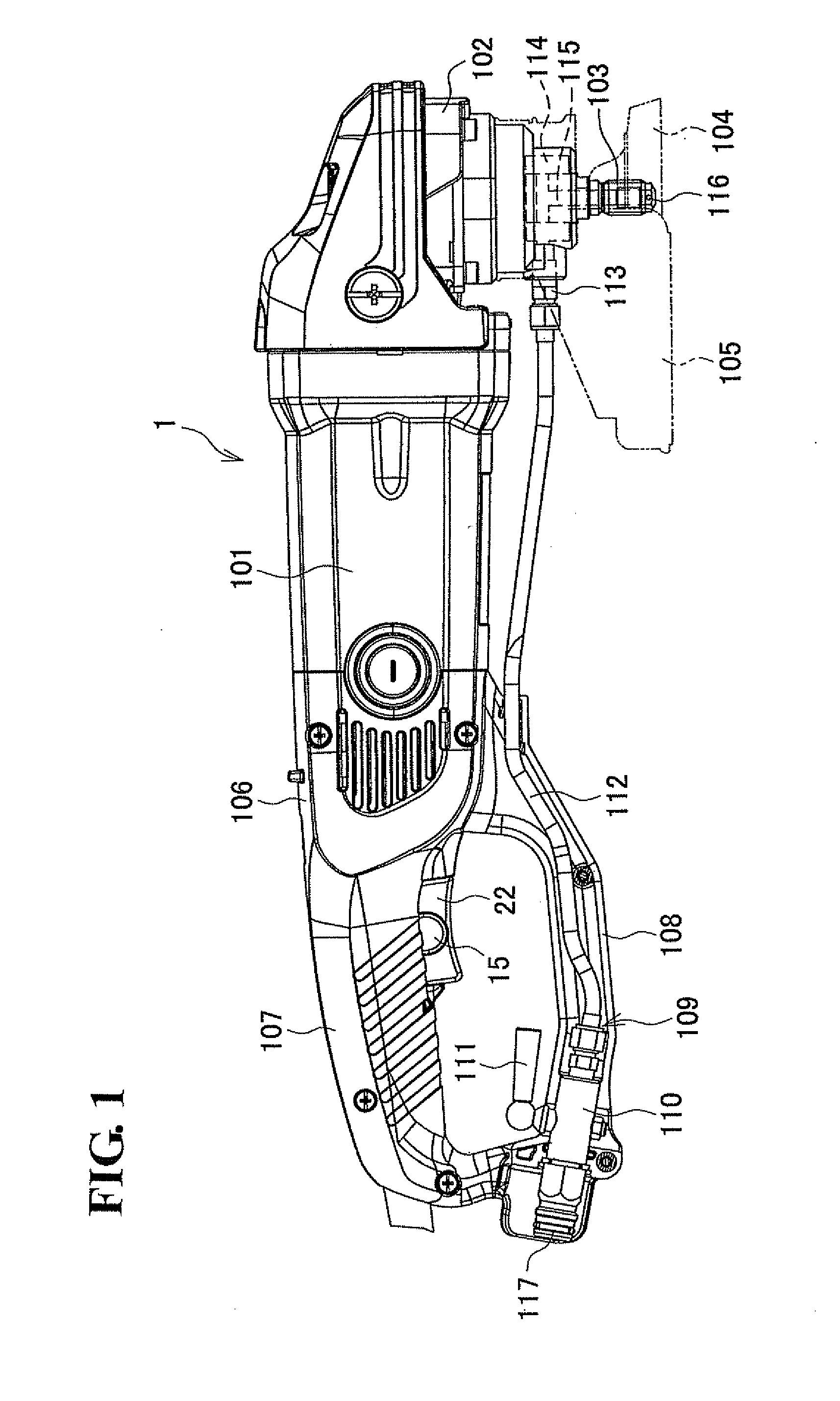
[0027]FIG. 1 shows a disc sander as an example of an electric power tool. The disc sander 1 includes a motor (not shown), a tubular motor housing 101 in which the motor is laterally disposed with an output shaft of the motor sticking out from the motor housing 101, a gear housing 102 connected at a front side (i.e., right-hand side of FIG. 1) of the motor housing 101, a rotary shaft 103 vertically and rotatably supported in the gear housing 102 with its upper end being connected to the output shaft through bevel gears and with its lower end sticking out from the bottom side of the gear housing 102, and a tool bit 104 such as a sanding disc attached to the lower end of the rotary shaft 103. Reference numeral 105 indicates a safety cover attached to a lower surface of the gear housing 102 and configured to cover a rear portion of the tool bit 104.

[0028]A handle housing...


PUM


Abstract

A seal structure for a switch mechanism includes a switch disposed in a housing, an operating member protruding forward from the housing through an opening formed in the housing and configured to turn on or off the switch, a rubber cover attached to the operating member from a front-side of the operating member and having a rear end engageable with the opening, and a fixing cover fixed to the operating member from outside the rubber cover so as to integrate the rubber cover with the operating member. In this seal structure, the rubber cover seals gap between the opening and the operating member.

Description

BACKGROUND OF THE INVENTION[0001]This application claims the entire benefit of Japanese Patent Application Number 2010-207024 filed on Sep. 15, 2010, the entirety of which is incorporated by reference.TECHNICAL FIELD[0002]The present invention relates to a seal structure provided in an electric power tool which includes a housing, a switch disposed in the housing, and a switch mechanism having an operating member protruding forward from the housing through an opening formed in the housing for turning on or off the switch, the seal structure sealing gap between the opening and the operating member. The present invention also relates to an electric power tool which employs the seal structure.BACKGROUND ART[0003]In equipment such as an electric power tool, a switch for operating a driving source such as a motor is disposed in a housing, and an operating member for turning on or off the switch (e.g., a trigger or a switch lever) protrudes forward from the housing through an opening form...

Claims


Application Information

Patent Timeline
Patent Type & Authority Applications(United States)
IPC IPC(8): H01H13/06
CPCB25F5/02H01H2009/048H01H13/06H01H9/22
Inventor KAWAKAMI, TAKAHIRO
Owner MAKITA CORP
Why Eureka
Try Eureka