Medium mounting device, medium reading device, and multifunction product

Active Publication Date: 2012-03-15
OKI DATA CORP
View PDF3 Cites 5 Cited by
  • Summary
  • Abstract
  • Description
  • Claims
  • Application Information

AI Technical Summary

Benefits of technology

[0011]According to the present invention, it is possible to easily take out t

Problems solved by technology

In the conventional image forming apparatus, when another unit is disposed above the discharge tray, it is difficult for the user to take out the medium placed on the discharge tray.
Further, in this case, when the user tries to take ou

Method used


Image

  • Medium mounting device, medium reading device, and multifunction product
  • Medium mounting device, medium reading device, and multifunction product
  • Medium mounting device, medium reading device, and multifunction product

Examples


Example

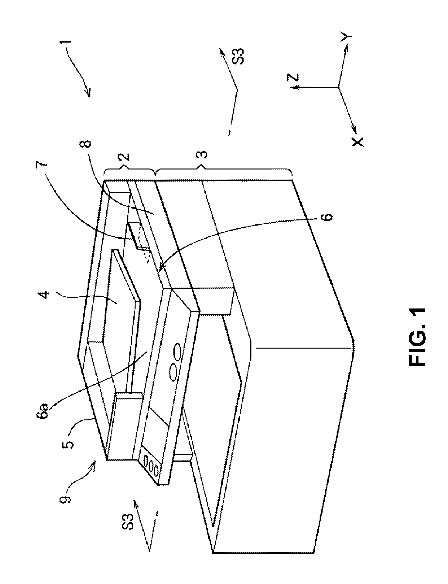
[0034]A first embodiment of the present invention will be explained. FIG. 1 is a schematic perspective view showing an outer appearance of a multifunction product 1 (also referred to as a multifunction peripheral or an MFP) according to the first embodiment of the present invention. As shown in FIG. 1, the multifunction product 1 includes a medium reading device 2 (also referred to as a document reading device or a medium reading portion) and a printer portion 3.

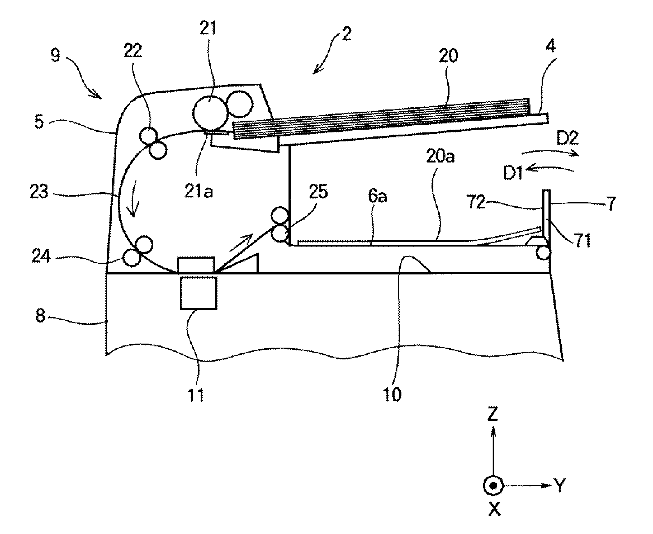
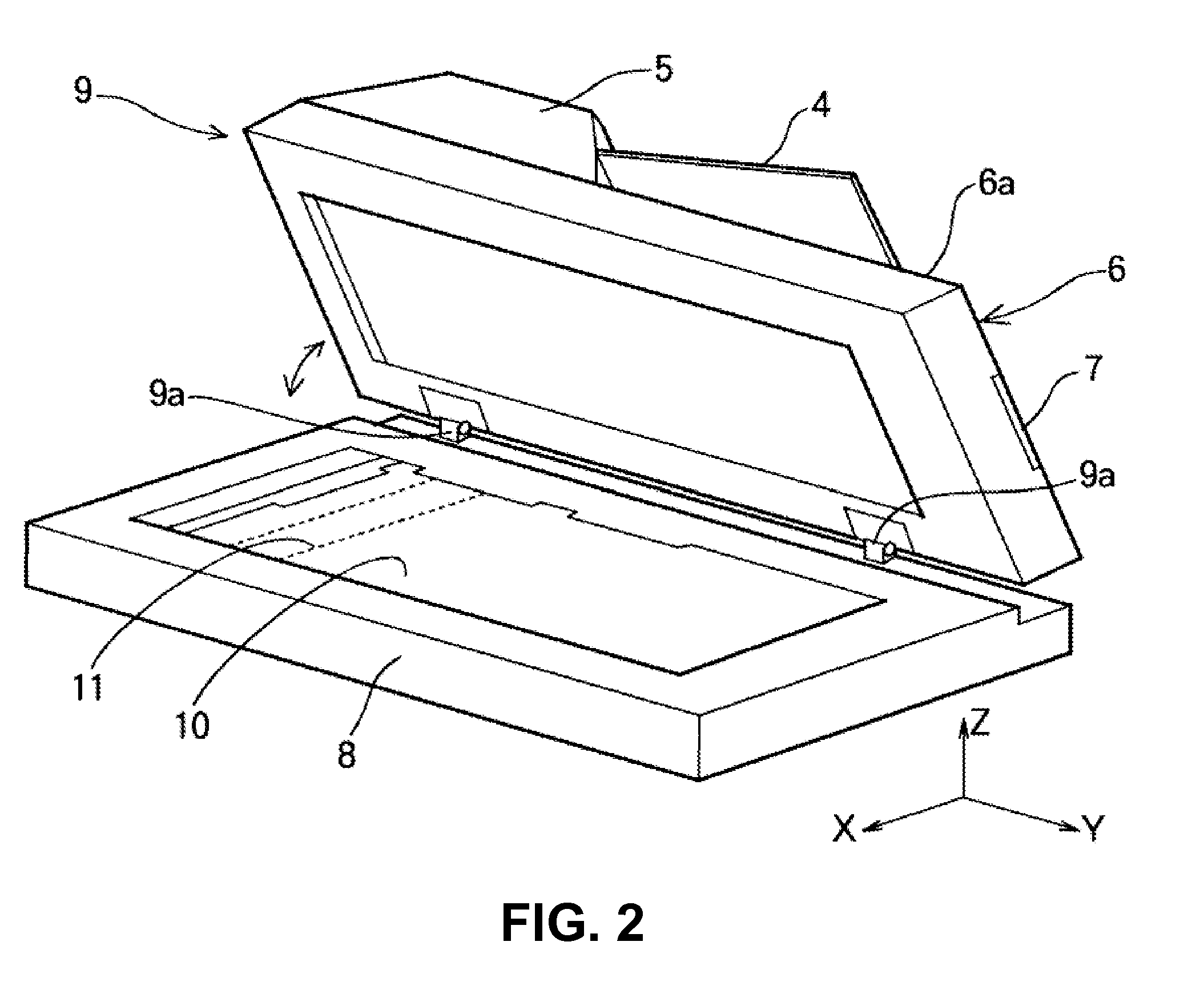
[0035]In the embodiment, the medium reading device 2 is provided for optically reading an image of a medium (also referred to as a document or a document sheet), and for transmitting image data obtained through reading to the printer portion 3. The medium reading device 2 includes a document tray 4 (also referred to as a sheet supply tray), a transportation portion 5, a medium mounting device 6, and a flat bed 8.

[0036]In the embodiment, the medium mounting device 6 includes a medium mounting portion 6a for placing and mounti...

Example

Second Embodiment

[0068]A second embodiment of the present invention will be explained next. In the second embodiment, different from the first embodiment, a medium mounting device 206 includes a medium mounting portion 206a. The medium mounting portion 206a includes a main portion 281 and an auxiliary portion (a tray auxiliary portion 282) disposed on the main portion 281 to be slidable. Further, different from the medium mounting device 6 in the first embodiment, a stopper portion 207 is disposed on the tray auxiliary portion 282 to be rotatable.

[0069]FIG. 15 is a schematic perspective view showing an outer appearance of a multifunction product 201 (an MFP 201) according to the second embodiment of the present invention. As shown in FIG. 15, the multifunction product 201 includes a medium reading device 202 and a printer portion 203.

[0070]In the embodiment, the medium reading device 202 is provided for optically reading an image of a document, and for transmitting image data obtain...


PUM


Abstract

A medium mounting device includes a medium mounting portion for placing a medium in a stacked state in a first direction, and a medium regulating portion arranged to be rotatable relative to the medium mounting portion. The medium regulating portion is arranged to regulate an edge portion of the medium when the medium regulating portion is in a rising state relative to the medium mounting portion. The medium regulating portion in the rising state is arranged to abut against the medium to rotate and retreat when the medium is taken out in a second direction different from the first direction.

Description

BACKGROUND OF THE INVENTION AND RELATED ART STATEMENT[0001]The present invention relates to a medium mounting device capable of mounting a medium in a stacked state, a medium reading device including the medium mounting device, and a multifunction product (MFP) including the medium mounting device.[0002]A conventional image forming apparatus is provided with a discharge tray as a medium mounting device. The discharge tray includes a medium receiving portion for regulating a leading edge of a medium discharged on the discharge tray in a medium regulation direction (that is, a direction opposite to a discharge direction of the medium), so that the medium is placed and aligned on the discharge tray. The medium receiving portion functions as a medium regulating portion for abutting against the leading edge of the medium (refer to Patent Reference). When the medium is taken out, a user picks upwardly the medium placed on the discharge tray.[0003]Patent Reference: Japanese Patent Publicat...

Claims


Application Information

Patent Timeline
IPC IPC(8): B65H31/26B65H5/26B65H7/02
CPCB65H31/20B65H31/26B65H2402/545B65H2402/546G03G15/602B65H2405/1124B65H2405/3321B65H2801/06B65H2801/39B65H2405/11164B65H2402/54
Inventor INO, SHIRO
Owner OKI DATA CORP
Why Eureka
Try Eureka