Liquid discharge head unit and image forming apparatus

a liquid discharge head and liquid drop technology, applied in the direction of printing, inking apparatus, etc., can solve the problems of inability to discharge liquid droplets in appropriate amounts, ink discharge malfunction, liquid droplets discharge in wrong directions or in inappropriate fashion, etc., to eliminate one or more problems.

Active Publication Date: 2012-03-15
RICOH KK
View PDF1 Cites 40 Cited by
  • Summary
  • Abstract
  • Description
  • Claims
  • Application Information

AI Technical Summary

Benefits of technology

[0012]Accordingly, it is a general object of at least one embodiment of the present invention to provide a liquid discharge head unit and an image forming apparatus having the liquid discharge head unit capable of reducing air bubble being mixed from the head tanks to heads, which substantially eliminate one or more problems caused by the limitations and disadvantages of the related art.

Problems solved by technology

In the liquid discharge recording type image forming apparatus, if air bubbles are mixed into the liquid discharge head (i.e., recording head), the liquid discharge head may discharge liquid droplets in wrong directions or may discharge in an inappropriate fashion.
Thus, if a dissolved oxygen rate of the ink is high, oxygen is gradually accumulated in the ink, which may eventually cause an ink discharge malfunction.
As a result, the heads may not be able to discharge appropriate amounts of the liquids (ink) or may not be able to discharge the liquids (ink) at all.
As described above, if the air bubbles are mixed into the liquid (ink) inside the head tanks, the recoding heads may not be able to appropriately discharge the ink, resulting in liquid discharge malfunctioning.

Method used


Image

  • Liquid discharge head unit and image forming apparatus
  • Liquid discharge head unit and image forming apparatus
  • Liquid discharge head unit and image forming apparatus

Examples


Embodiment Construction

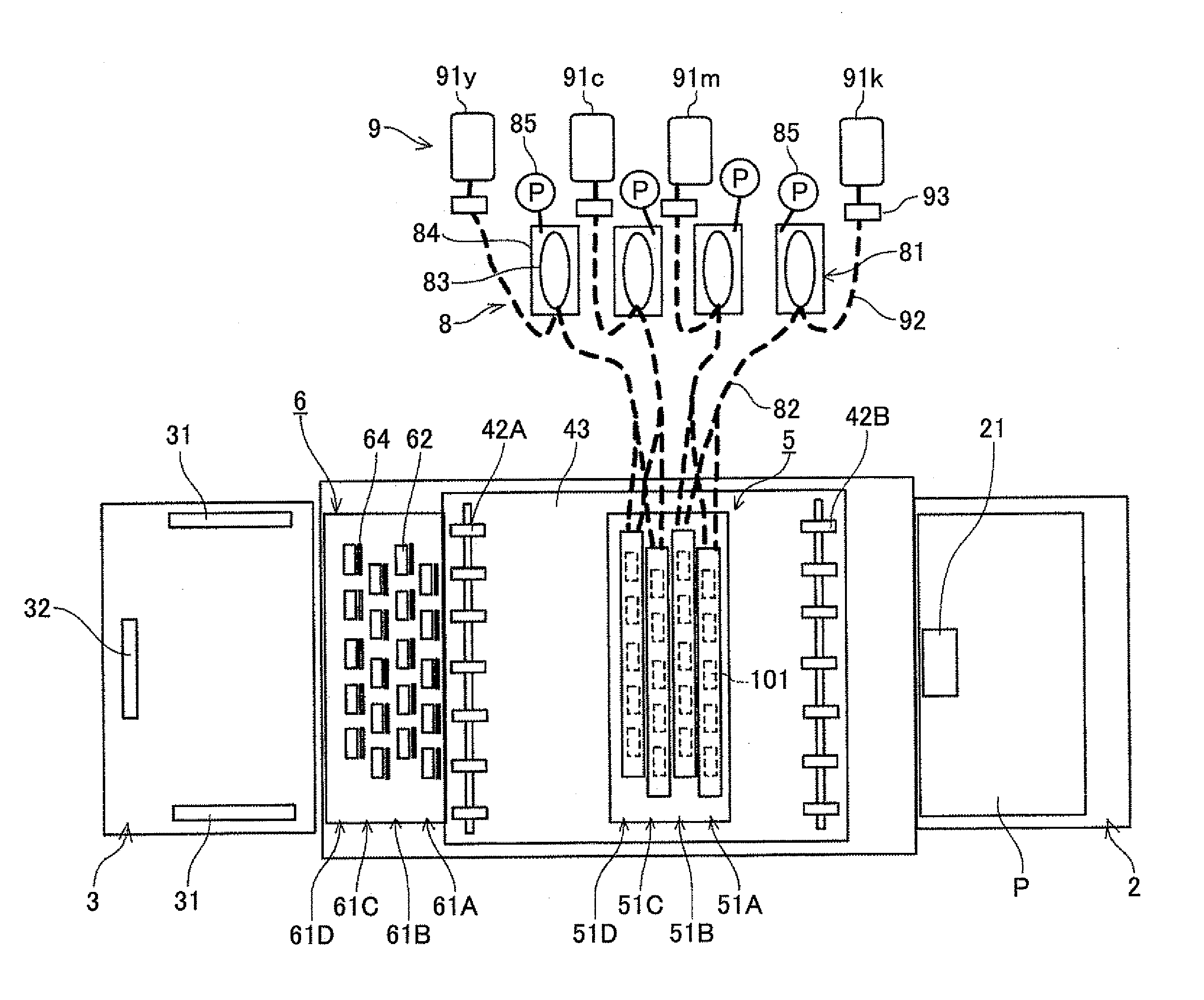
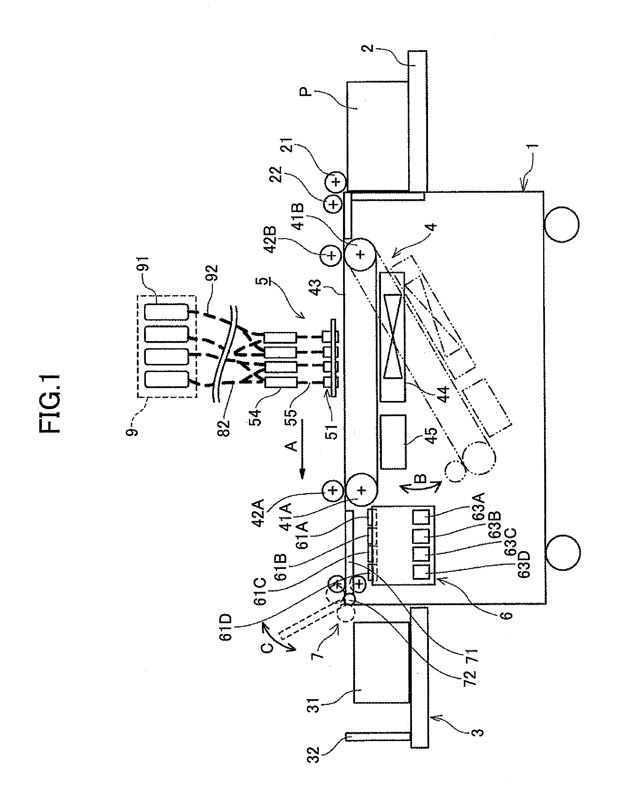
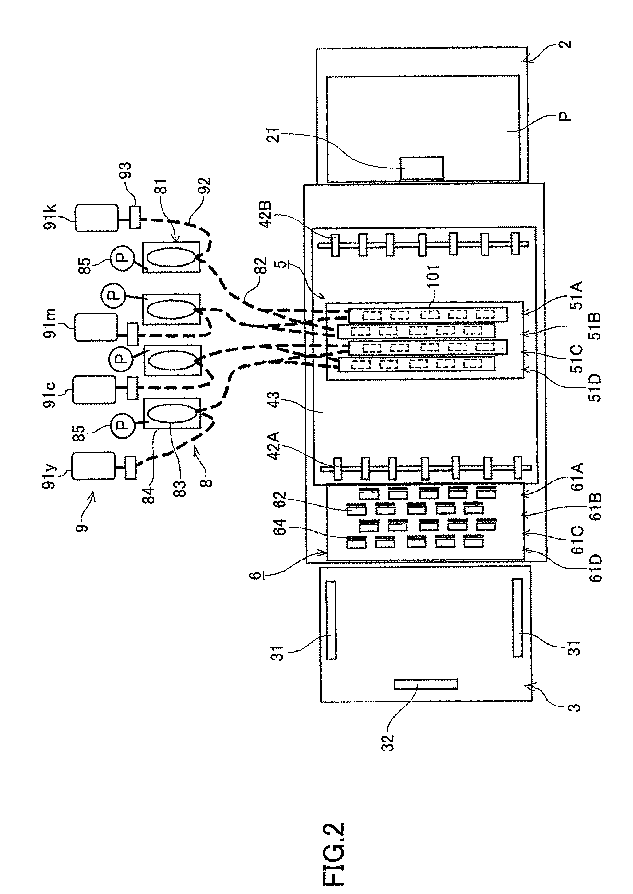
[0035]In the following, preferred embodiments will be described with reference to the accompanying drawings. First, an example of an image forming apparatus according to an embodiment is described with reference to FIGS. 1 and 2. Note that FIG. 1 is a schematic configuration diagram illustrating an overall configuration of the image forming apparatus according to an embodiment and FIG. 2 is a schematic plan diagram illustrating the image forming apparatus of FIG. 1.

[0036]The image forming apparatus according to an embodiment is a line-type image forming apparatus that includes a main body 1, a paper feed tray 2 configured to accumulate sheets P and feed the sheet one at each feed, an output tray 3 configured to accumulate the printed sheets P, a transfer unit 4 configured to transfer the sheet P from the paper feed tray 2 to the output tray 3, an image forming unit 5 having head modules 51 forming recording heads configured to carry out printing by discharging liquid droplets onto t...


PUM


Abstract

A liquid discharge head unit includes a liquid container tank storing a liquid and a head discharging liquid droplets from its nozzles. The head includes a common channel supplying the liquid to liquid-chambers communicating with the nozzles, and the common channel includes a supply port introducing the liquid and a discharge port discharging the liquid. The liquid container tank includes a container including upstream and downstream chambers separated via a filtering member, a supply path supplying the liquid from the downstream chamber to the supply port of the head, a discharge path discharging the liquid obtained from the discharge port of the head, a communication path via which the downstream chamber communicates with the discharge path, and a communication path via which the upstream chamber communicates with the discharge path, where a fluid resistance of the second communication path is higher than that of the first communication path.

Description

BACKGROUND OF THE INVENTION[0001]1. Field of the Invention[0002]The disclosures herein relate to a liquid discharge head unit and an image forming apparatus.[0003]2. Description of the Related Art[0004]An inkjet recording apparatus is generally known as a liquid discharge recording type image forming apparatus, such as a printer, a facsimile machine, or a plotter, or a combination of these functions, that includes a recording head formed, for example, of a liquid discharge head (liquid droplet discharge head) discharging liquid droplets. The liquid discharge recording type image forming apparatus is configured to discharge ink droplets from its recording head onto a transferred sheet, thereby forming an image on the transferred sheet. The formation of the image includes recording, printing, and imaging. There are two types of the liquid discharge image forming apparatus including: 1) a serial type image forming apparatus in which the recording head discharges ink droplets onto the t...

Claims


Application Information

Patent Timeline
Patent Type & Authority Applications(United States)
IPC IPC(8): B41J2/175
CPCB41J2202/12B41J2/17509
Inventor TSUBAKI, KENGO
Owner RICOH KK
Why Eureka
Try Eureka