Developing device, image forming apparatus, and image forming method

a technology of developing devices and forming methods, applied in electrographic process devices, instruments, optics, etc., can solve problems such as increased costs, and achieve the effect of eliminating one or more problems

Inactive Publication Date: 2014-11-25
RICOH KK
View PDF10 Cites 0 Cited by
  • Summary
  • Abstract
  • Description
  • Claims
  • Application Information

AI Technical Summary

Benefits of technology

[0008]It is a general object of at least one embodiment of the present invention to provide a developing device, an image forming apparatus and an image forming method capable of regulating a toner layer at a predetermined thickness without having a direct-current power supply for supplying a direct voltage specifically to a toner layer thickness regulator member, which substantially eliminate one or more problems caused by the limitations and disadvantages of the related art.

Problems solved by technology

However, if the image forming apparatus having the hopping developing system is further provided with a direct-current (DC) power supply in addition to the above power supply to generate a periodic pulse voltage, the cost may be increased.

Method used


Image

  • Developing device, image forming apparatus, and image forming method
  • Developing device, image forming apparatus, and image forming method
  • Developing device, image forming apparatus, and image forming method

Examples


Embodiment Construction

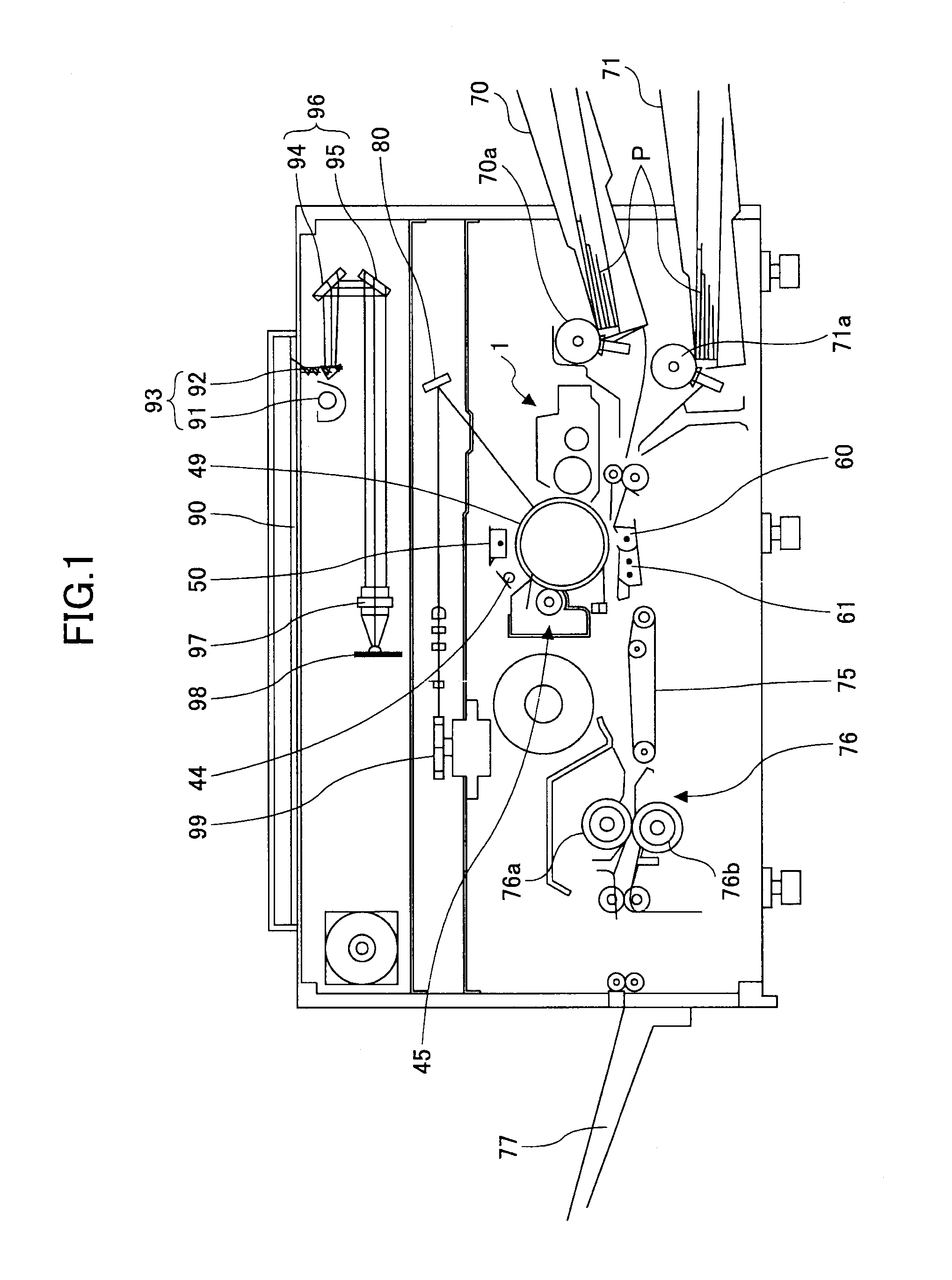
[0034]In the following, embodiments of the present invention will be described with reference to the accompanying drawings. An image forming apparatus according to an embodiment utilized as a copier employs a hopping developing system. FIG. 1 is a schematic configuration diagram illustrating the copier according to an embodiment. The copier according to an embodiment includes a photoreceptor drum 49 as a latent image carrier, which is rotationally driven in a clockwise direction in FIG. 1. When an operator places a document (not illustrated) on a contact glass 90 and presses a print-start switch (not illustrated), a document image is read while moving a first scanner system 93 having a document light source 91 and a mirror 92 and a second scanner system 96 having mirrors 94 and 95. The document image scanned is then read as an image signal by an image reader 98 arranged at a rear side of a lens 97, and the read image signal is converted into a digital signal utilized for image proce...


PUM


Abstract

An image forming apparatus includes a latent image carrier to carry a latent image, a developing device having a toner carrier with first and second electrodes to develop the latent image by transferring the toner to a developing region between the toner carrier and the latent image carrier while causing the toner to hop between the first and second electrodes and attaching the hopping toner to the latent image, a pulsed power supply to output a first periodic pulse voltage having a mean potential the same as a normal toner charge and a second periodic pulse voltage, a smoothing circuit to make the first periodic pulse voltage smooth to generate a direct voltage, and a toner layer thickness regulator member to regulate, on receiving the direct voltage, a thickness of the toner layer in a region between a toner supply position at which toner is supplied and the developing region.

Description

BACKGROUND OF THE INVENTION[0001]1. Field of the Invention[0002]The disclosures herein relate to a developing device, an image forming apparatus and an image forming method for developing an image in a hopping developing system by attaching a toner hopping on a surface of a toner carrier to a latent image formed on a latent image carrier.[0003]2. Description of the Related Art[0004]Japanese Patent Application Publication No. 2008-008929 (hereinafter called “Patent Document 1”) discloses one example of an image forming apparatus configured to develop an image in a hopping developing system. The disclosed image forming apparatus includes a developing device that includes a toner carrier roller formed of a rotatable cylindrical base and two or more electrodes adjacently arranged at a predetermined pitch along a periphery of the cylindrical base. In the image forming apparatus, a first periodic pulse voltage and a second periodic pulse voltage respective phases of which are shifted from...

Claims


Application Information

Patent Timeline
Patent Type & Authority Patents(United States)
IPC IPC(8): G03G15/08G03G15/06
CPCG03G2215/0651G03G15/0818
Inventor HIROTA, TETSUROKOSUGI, HIDEKIYAMADA, MASAAKIKUROKAWA, ATSUSHISEKI, HIDEYASUISHII, YASUYUKI
Owner RICOH KK
Why Eureka
Try Eureka