Eureka AIR delivers breakthrough ideas for toughest innovation challenges, trusted by R&D personnel around the world.

Double lumen catheter

a catheter and lumen technology, applied in the field of double lumen catheters, can solve the problems of reducing the efficiency of blood treatment process, catheters made of relatively stiff materials, and unsuitable for long-term placemen

Inactive Publication Date: 2012-03-15
JOLINE
View PDF7 Cites 9 Cited by
  • Summary
  • Abstract
  • Description
  • Claims
  • Application Information

AI Technical Summary

Benefits of technology

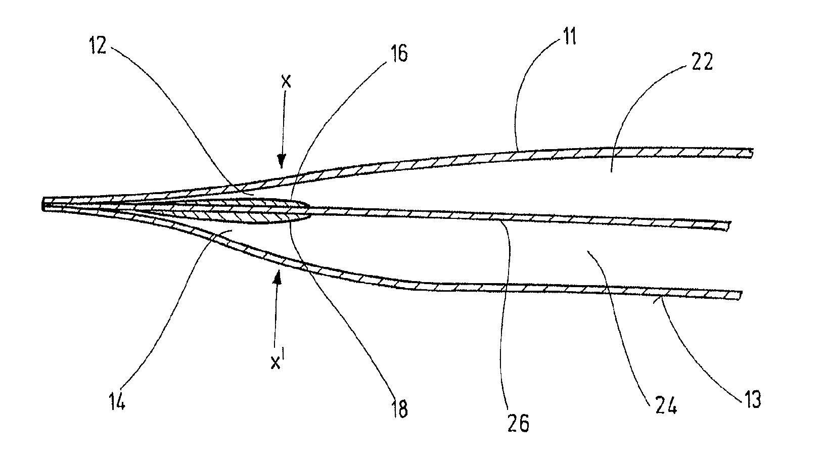
[0017]With the at least one ridge extending in the area of the openings and along a longitudinal portion of the tubular body of the catheter, the inflow and / or the return of the blood is directed to the respective opening comprising the ridges. With the at least one ridge at the opening of the intake lumen the intake of the blood flow is actively guided into the lumen. On the other hand—or at the same time—with the at least one ridge being present at the opening of the return lumen, it is assured that the blood leaving the return lumen—and entering the vessel—is not being taken up by the opening of the intake lumen since the ridge provide for a directed outflow of the blood away from the openings of the catheter.
[0028]This measure has the advantage that the flow characteristics of the blood entering and / or leaving the intake and / or return lumen respectively, can fully be taken into consideration. Thus, in one embodiment of the invention it is preferred if more than one ridge is present in the area of one opening, that one of the ridges extends to the very distal end of the catheter whilst one or more other ridges do not. Similar, according to another embodiment of the invention, and in case the divider wall at the distal end of the tubular body comprises in the area of both, the side facing the intake lumen and the side facing the return lumen, at least one ridge extending in the area of the openings and along a longitudinal portion of the tubular body, one of the ridges may extend from the very distal end of the catheter along a longitudinal portion of the tubular body, whereas one or more others do not, but rather extend from a certain distance of the very end of the catheter along the longitudinal portion of the tubular body.

Problems solved by technology

In hemodialysis cases where the blood is not adequately treated, a number of adverse effects result from incomplete elimination of toxins from the blood.
This so-called recirculation reduces the efficiency of the blood treatment process.
However, in order to keep its shape during high flow rate dialysis, the catheter is made of a relatively stiff material which is unsuitable for long-term placement.
Further, when using stiff material, the risk of causing kinking of the catheter is high if the catheter gets bent more than 180°, resulting in obstruction, splitting and may be responsible for vein penetration injuries.
Despite the various solutions suggested and / or provided in the state of the art for double lumen catheters, the problems of recirculation, clotting, inadequate flow rates remain.

Method used


Image

  • Double lumen catheter
  • Double lumen catheter
  • Double lumen catheter

Examples


Embodiment Construction

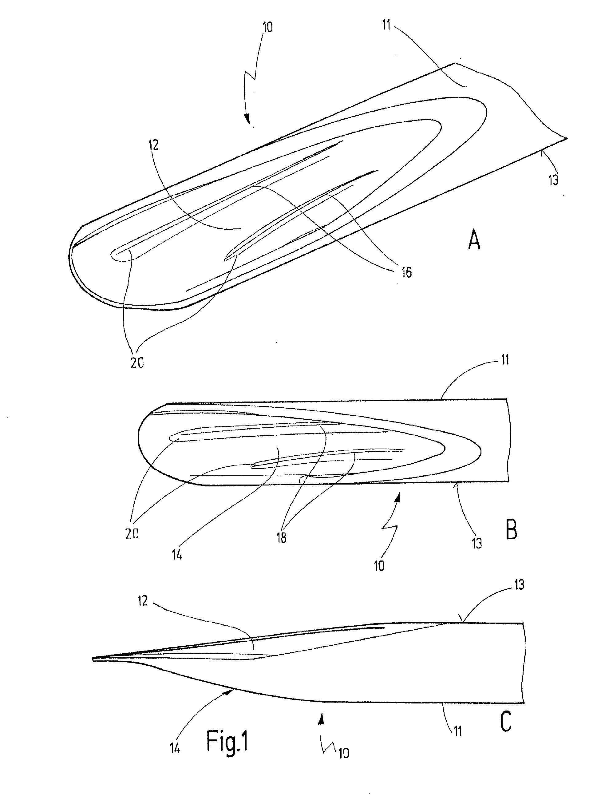
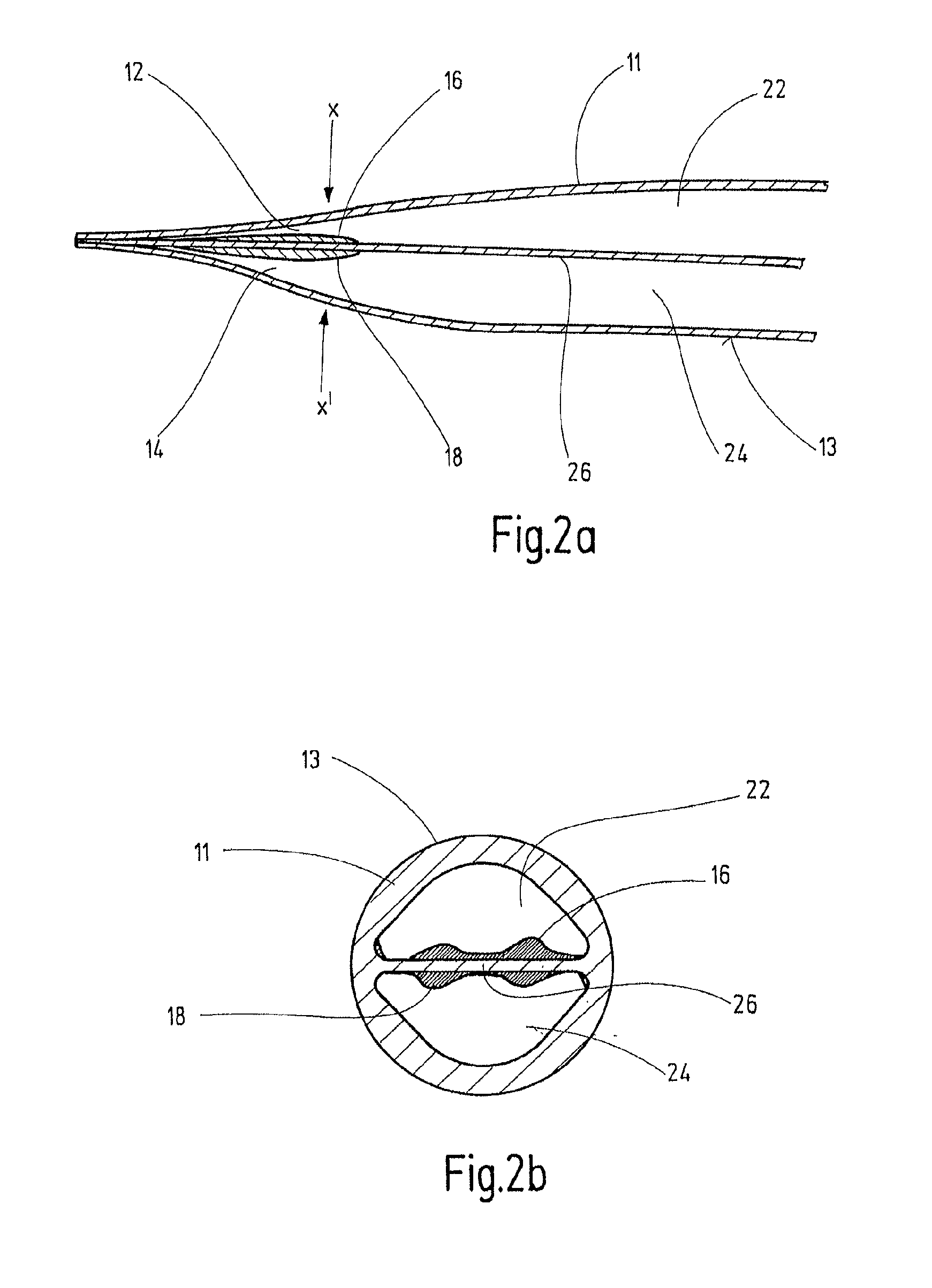
[0052]FIG. 1 shows the distal end of a double lumen catheter according to an embodiment of the invention, with its elongated tubular body 11 being depicted in part. In FIG. 1, a double lumen catheter tip 10 of an embodiment according to the invention is shown, with the opening of intake lumen 22 being designated as 12, as it is depicted in FIG. 1a, and the opening of return lumen 24 as 14, as it is depicted in FIG. 1b. The openings 12 and 14 are separated via a divider wall (not pictured in FIG. 1). FIG. 1c shows a side view of the tip 10, showing the openings 12 and 14 of both, the intake 22 and the return lumen 24. In the embodiment shown in FIG. 1, the tip 10 comprises ridges 16 and 18, extending in the area of the openings 12 and 14 of the intake 22 and the return lumen 24 and along a longitudinal portion of the tubular body. In the embodiment shown in FIG. 1, the distal ends 20 of the ridges 16 start to raise / incline in a certain, short distance from the very end of the tip. As...


PUM


Abstract

The present invention concerns a double-lumen catheter and a method for delivering or withdrawing fluids to / from a patient, in particular for use in hemodialysis. The double-lumen catheter comprises an elongated tubular body having a proximal end and distal end, with the distal end being positionable within a vessel of a patient, a divider wall extending along an interior of said tubular body and separating said interior into an intake lumen and a return lumen. The intake lumen and said return lumen each comprise an opening sloping toward the divider wall and toward the distal end of the tubular body, respectively, the openings.

Description

CROSS REFERENCES TO RELATED APPLICATIONS[0001]This application is a continuation of international patent application PCT / EP2010 / 001530, filed on Mar. 11, 2010 and designating the U.S., which international patent application has been published in English language and claims priority from European patent application 09155018.6, filed on Mar. 12, 2009. The entire contents of these priority applications are incorporated herein by reference.BACKGROUND OF THE INVENTION[0002]The present invention concerns a double lumen catheter for use in the delivery or the withdrawal of fluids to a patient, the catheter comprising an elongated tubular body having a divider wall extending along an interior of said tubular body and separating said interior into an intake lumen and a return lumen.[0003]Double lumen catheter of this kind are generally known in the state of the art and are used in medical applications, where two separate fluid flow paths are necessary for the treatment of a patient. In parti...

Claims


Application Information

Patent Timeline
IPC IPC(8): A61M25/14
CPCA61M25/003A61M25/0032A61M25/0068A61M1/3661A61M2025/0031A61M2025/0073A61M25/0071
Inventor STEEGERS, ANSELMSCHULER, OLIVER
Owner JOLINE
Why Eureka
Eureka Blog
Learn More