
Double lumen tubing with improved kinking resistance

a double-lumen, kinking-resistant technology, applied in the direction of multi-lumen catheters, catheters, etc., can solve the problems of impaired lumen of a catheter tube designed in this way, adverse effects on the potential fluid flow through the catheter tube, and complications and malfunctions, so as to improve the kinking resistance of the catheter tube, improve the kinking resistance, and facilitate manufacturing

Inactive Publication Date: 2012-03-15
JOLINE
View PDF1 Cites 2 Cited by
  • Summary
  • Abstract
  • Description
  • Claims
  • Application Information

AI Technical Summary

Benefits of technology

The technical effect of this patent is that it addresses the issue of kinking (when a catheter becomes blocked) in various ways but acknowledges the need for alternatives that are easier to make.

Problems solved by technology

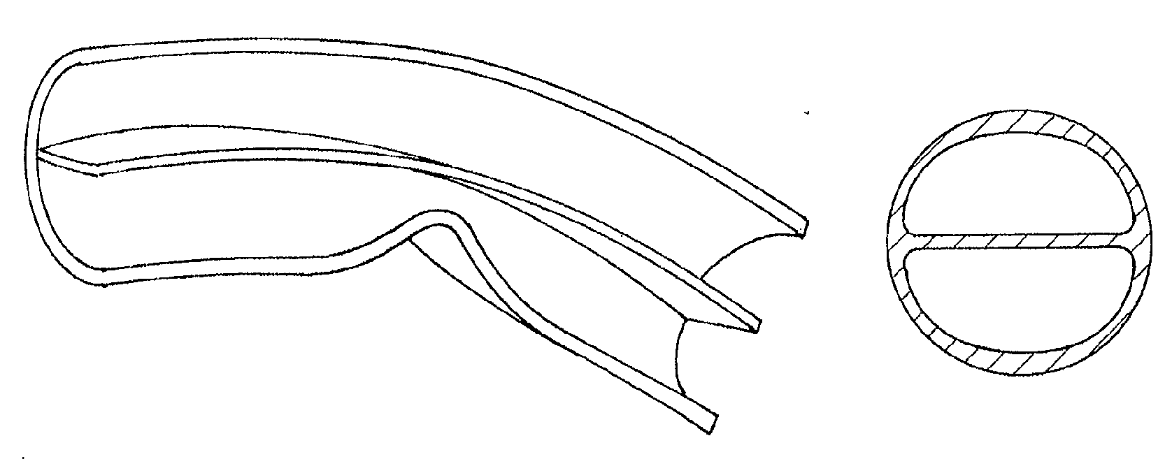
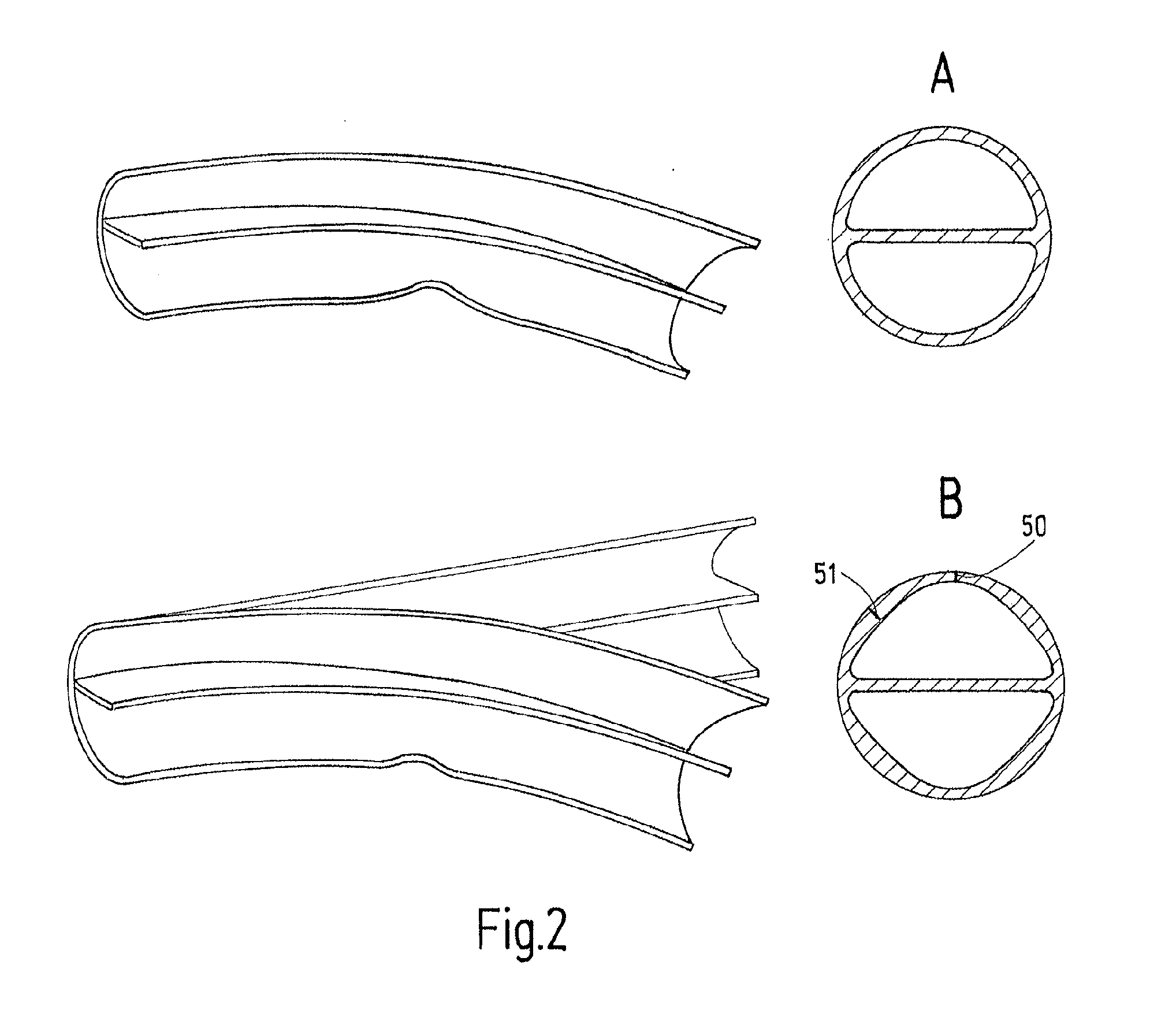
The technical problem addressed in this patent is the kinking resistance of double lumen catheters, which can lead to complications and malfunctions during the operation of medical devices which use a catheter of this kind. Existing solutions such as increased wall thicknesses or the use of reinforcing materials have either impaired the lumen area or increased manufacturing costs. The invention provides a new approach to overcome this problem.

Method used


Image

  • Double lumen tubing with improved kinking resistance
  • Double lumen tubing with improved kinking resistance
  • Double lumen tubing with improved kinking resistance

Examples


Embodiment Construction

[0044]The double lumen catheter tube according to the invention is designed for use as a catheter, and it may be used with any catheter device in any application where a double lumen catheter is needed.

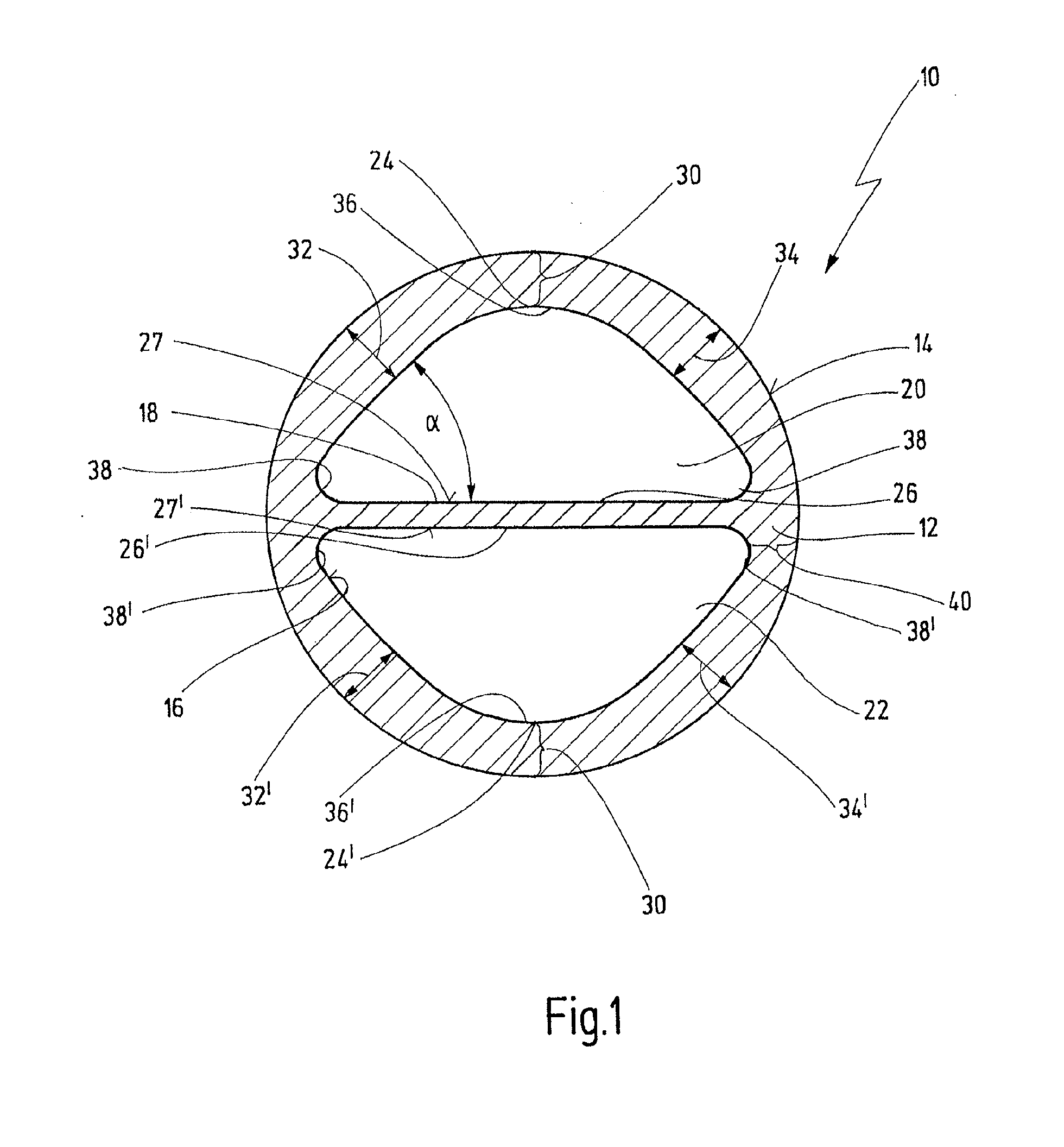
[0045]A first preferred embodiment according to the invention is shown in general with number 10 in FIG. 1. The double lumen catheter tube body 10 includes a tubular wall 12, which has an outer surface 14 and an inner surface 16. The catheter tube body 10 also comprises an inner or divider wall 18, dividing the lumen of the catheter tube body 10 in two lumens, a first lumen 20 and a second lumen 22. Thus, each of the lumens 20 and 22 is defined by the inner surface 16 of the tubular wall body 12 and the inner (or divider) wall 18.

[0046]The cross-sectional area of each of the lumens 20, 22 comprises an arcuated portion 24, 24′ and a substantially plane portion 26, 26′ opposite to the respective arcuated portion 24, 24′, the plane portion 26, 26′ being defined by the surface 27, 27′ of ...


PUM


Abstract

The present invention relates to a double lumen catheter tube having a substantially circular cross-section and comprising a catheter tube body having a longitudinal axis, and further comprising an outer tubular and an inner divider wall inside the catheter tube body dividing said catheter tube body into a first and a second lumen. The first and the second lumen each comprise a cross section having the shape of an isosceles triangle with three rounded vertices. The tubular wall comprises wall sections that have a smaller wall thickness.

Description


Claims


Application Information

Patent Timeline
Owner JOLINE
Learn More