Axial Winding Motor

Inactive Publication Date: 2012-03-22
SUNONWEALTH ELECTRIC MACHINE IND
View PDF7 Cites 4 Cited by
  • Summary
  • Abstract
  • Description
  • Claims
  • Application Information

AI Technical Summary

Benefits of technology

[0007]It is therefore the primary objective of this invention to provide an

Problems solved by technology

Also, the axial-winding motor w

Method used


Image

  • Axial Winding Motor
  • Axial Winding Motor
  • Axial Winding Motor

Examples


Embodiment Construction

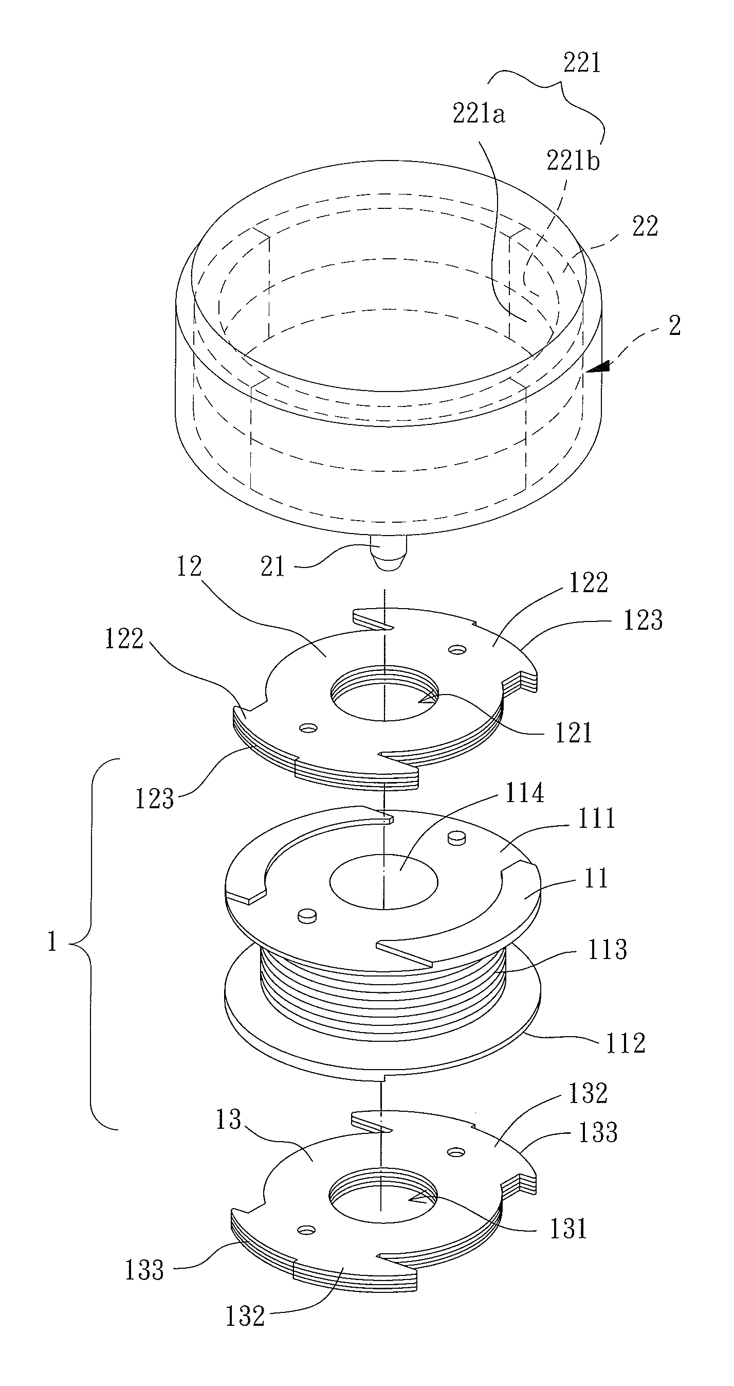
[0021]Referring to FIG. 4, an exploded view of an axial-winding motor is shown according to a preferred embodiment of the invention. The axial-winding motor includes a stator 1 and a rotor 2. The stator 1 receives currents and generates magnetic forces. The rotor 2 is disposed in accordance with the stator 1 and may be driven to rotate by the magnetic forces generated by the stator 1.

[0022]Specifically, referring to FIGS. 4 and 5, the stator 1 includes a winding assembly 11, a first magnetic-conducting plate 12 and a second magnetic-conducting plate 13. The winding assembly 11 extends in an axial direction of the stator 1 and includes a first axial face 111, a second axial face 112, a winding 113 and an axial hole 114. The first axial face 111 and the second axial face 112 are located on two ends of the winding assembly 11 in the axial direction. The winding 113 is wound around the winding assembly 11 between the first axial face 111 and the second axial face 112. The axial hole 114...


PUM


Abstract

An axial-winding motor includes a stator and a rotor. The stator has a winding assembly, a first magnetic-conducting plate and a second magnetic-conducting plate. The first and second magnetic-conducting plates are coupled with two ends of the winding assembly in an axial direction of the winding assembly. The first magnetic-conducting plate includes a plurality of first pole pieces on an outer periphery thereof, and the second magnetic-conducting plate includes a plurality of second pole pieces on an outer periphery thereof. The rotor is rotatably coupled with the stator and has a plurality of magnetic pole faces facing the stator. One of the first pole pieces is at least partially overlapped with adjacent one of the second pole pieces in an axial direction of the stator.

Description

BACKGROUND OF THE INVENTION[0001]1. Field of the Invention[0002]The present invention generally relates to an axial-winding motor and, more particularly, to an axial-winding motor that has low axial vibration.[0003]2. Description of the Related Art[0004]Referring to FIGS. 1 to 3, a conventional axial-winding motor including a stator 8 and a rotor 9 is shown. The stator 8 receives currents and generates magnetic forces. The rotor 9 is disposed in accordance with the stator 8 and may be driven to rotate by the magnetic forces generated by the stator 8.[0005]Specifically, the stator 8 includes a winding assembly 81, a first magnetic-conducting plate 82 and a second magnetic-conducting plate 83. The winding assembly 81 includes a winding 811 extending in an axial direction of the stator 8. The first magnetic-conducting plate 82 is disposed on one end of the winding assembly 81 in the axial direction and includes two pole pieces 821 and two excitation faces 822. The pole pieces 821 are l...

Claims


Application Information

Patent Timeline
IPC IPC(8): H02K1/27
CPCH02K1/145H02K29/03H02K21/22
Inventor HORNG, ALEXCHEN, YEN-MINGCHENG, CHUNG-KEN
Owner SUNONWEALTH ELECTRIC MACHINE IND
Why Eureka
Try Eureka