Optical sensor for printer media motion detection

an optical sensor and motion detection technology, applied in printing, other printing apparatus, etc., can solve the problems of misidentification of print media type, inability to detect the slippage of the media with respect to the drive system, etc., to achieve accurate measurement of the motion of the print media, enabling accurate reading of the media markings, and greater accuracy

Inactive Publication Date: 2012-03-22
EASTMAN KODAK CO
View PDF1 Cites 9 Cited by
  • Summary
  • Abstract
  • Description
  • Claims
  • Application Information

AI Technical Summary

Benefits of technology

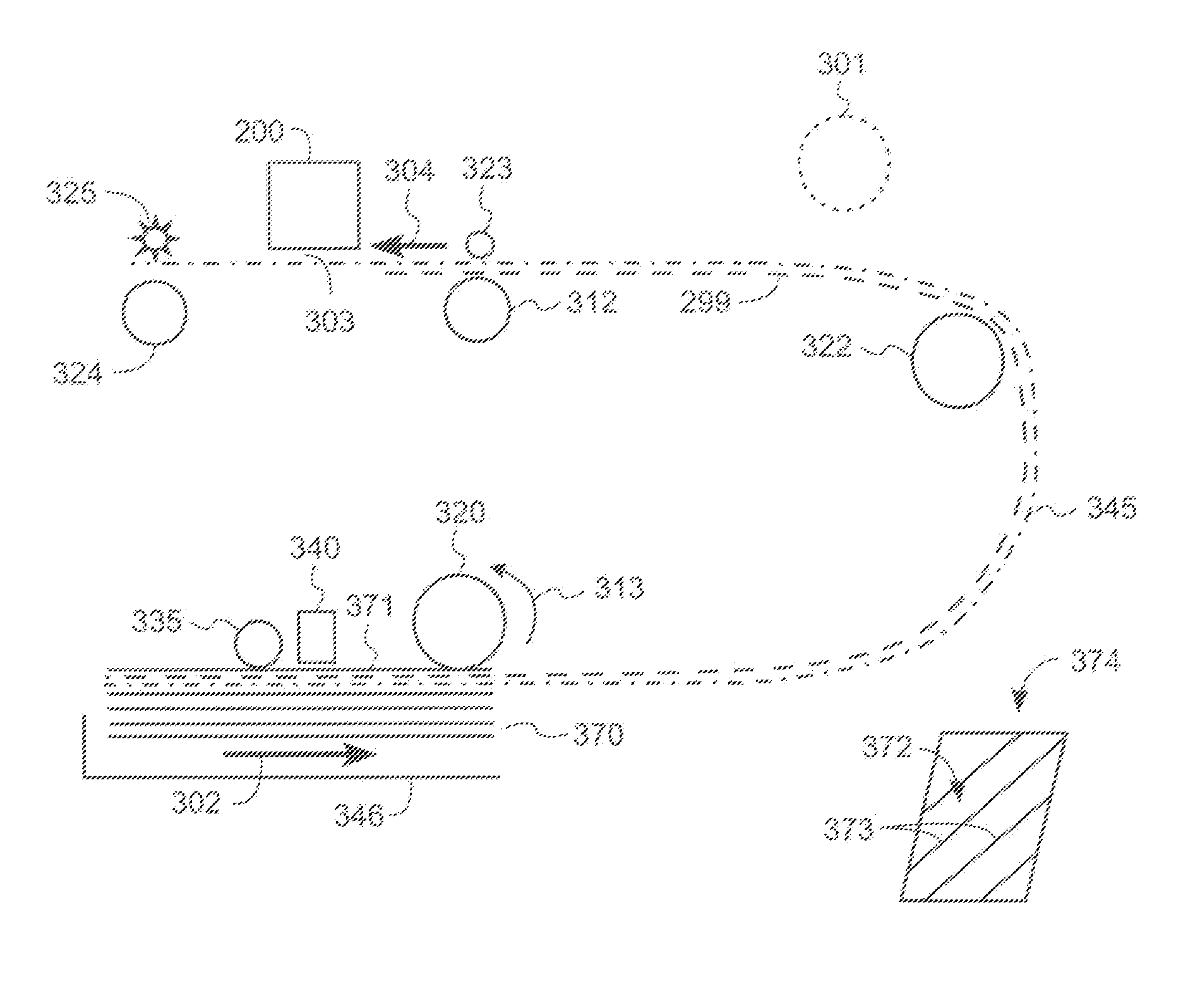
[0011]The present invention has the advantage of providing accurate measurement of the motion of the print media for enabling accurate reading of the media markings, such as bar codes, on the print media. A first source of unreliability in the identification of media markings is media slip during advance of the media. In typical carriage printers, a rotary encoder is provided in association with one of the media advance rollers, such as the feed roller. The amount of rotation of the encoder (and its associated roller) is monitored and is related to the nominal distance of media advance by Rθ, where R is the radius of the associated roller plus the media thickness. However, this nominal distance of media advance will be in error if the media slips relative to the roller during media advance, and / or if the wrong thickness of media is assumed. A second source of unreliability in the identification of the media markings is media skew; in particular, if the media markings are not oriented perpendicular to the media advance direction. The distance between media markings as detected by the barcode sensor will depend upon the orientation of the media markings relative to the media advance direction. Direct sensing provides greater accuracy (compared with the prior art drive system encoder) in terms of delivering the leading edge to a predetermined position. In addition, a direct sensing encoder, in combination with the prior art drive system encoder, provides an ability to quickly detect when a paper miss-feed has occurred. If the paper should stall after motion begins, or if motion does not begin when anticipated, the lack of motion can be quickly discerned by the lack of motion signal from the optical sensor.

Problems solved by technology

Furthermore, lacking a means of directly sensing movement of the media, any slippage of the media with respect to the drive system is not apparent via the encoder of the prior art.
Any slippage of the print media as it is being read by the barcode reader can cause the type of print media to be misidentified.

Method used


Image

  • Optical sensor for printer media motion detection
  • Optical sensor for printer media motion detection
  • Optical sensor for printer media motion detection

Examples


Embodiment Construction

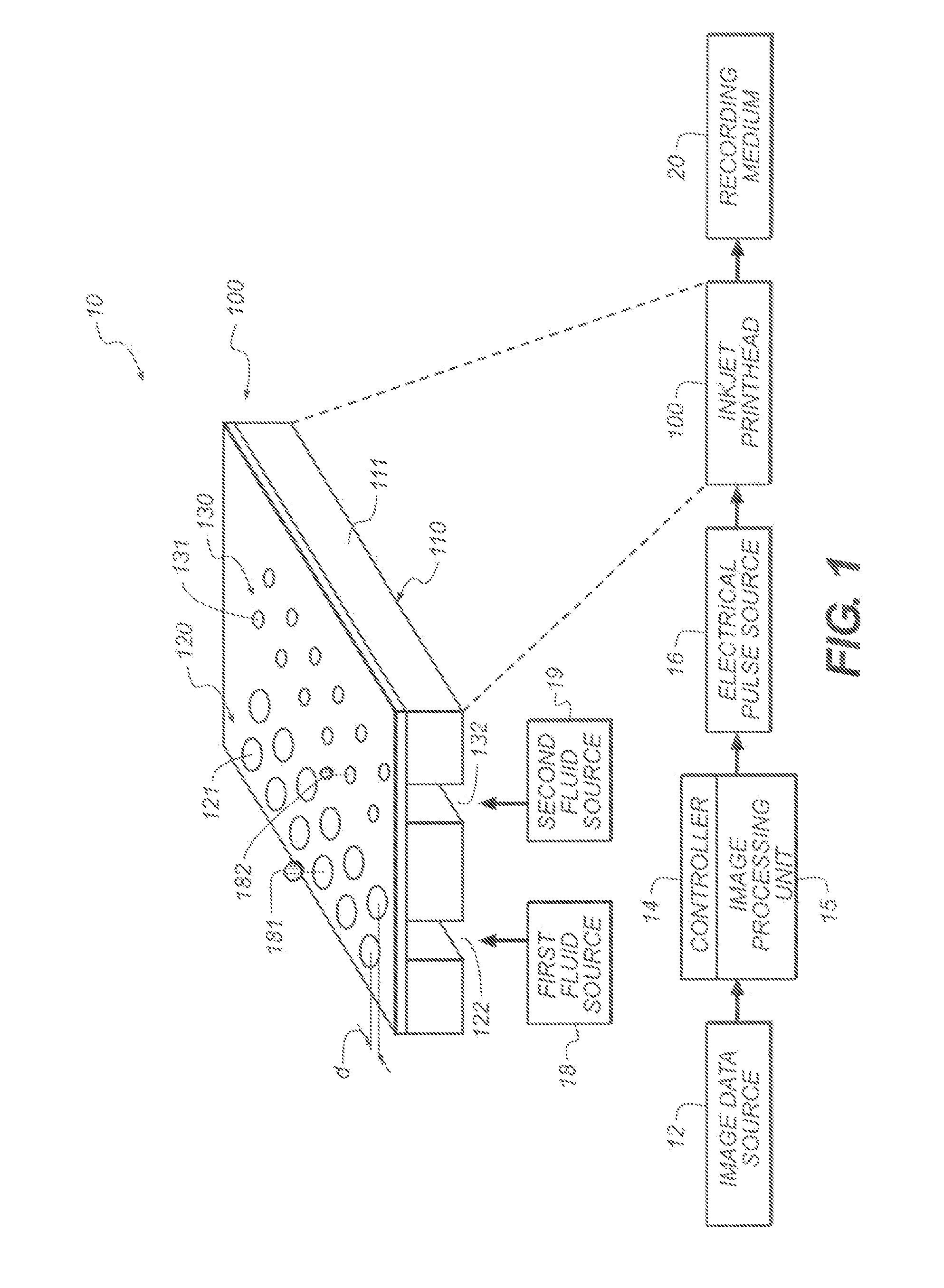
[0022]Referring to FIG. 1, a schematic representation of an inkjet printer system 10 is shown for its usefulness with the present invention and is fully described in U.S. Pat. No. 7,350,902, which is incorporated by reference herein in its entirety. Inkjet printer system 10 includes an image data source 12, which provides data signals that are interpreted by a controller 14 as being commands to eject drops. Controller 14 includes an image processing unit 15 for rendering images for printing, and the controller 14 outputs signals to an electrical pulse source 16 of electrical energy pulses that are inputted to an inkjet printhead 100, which includes at least one inkjet printhead die 110.

[0023]In the example shown in FIG. 1, there are two nozzle arrays. Nozzles 121 in the first nozzle array 120 have a larger opening area than nozzles 131 in the second nozzle array 130. In this example, each of the two nozzle arrays has two staggered rows of nozzles, each row having a nozzle density of...


PUM


Abstract

An inkjet printer includes a paper tray for holding print media; a pick-up roller for moving the print media along at least a portion of a pre-print zone of a paper transport path; a light source disposed along the pre-print zone of the paper transport path that directs light toward a non-print side of the print media for illuminating the non-print side of the print media; and an array sensor that receives reflected light from the non-print side of the print media; wherein data from the sensor is used to determine an amount of motion of the print media in the pre-print zone.

Description

CROSS REFERENCE TO RELATED APPLICATIONS[0001]Reference is made to commonly assigned U.S. patent application Ser. No. 12 / 871,068 filed Aug. 30, 2010 by Rzadca et al., entitled “Encoder for Inkjet Printers”, the disclosure of which is herein incorporated by reference.FIELD OF THE INVENTION[0002]The present invention generally relates to encoders for inkjet printers. More specifically, the present invention relates to using an optical encoder for sensing the motion of the print media.BACKGROUND OF THE INVENTION[0003]An inkjet printing system typically includes one or more printheads and their corresponding ink supplies. Each printhead includes an ink inlet that is connected to its ink supply and an array of drop ejectors, each ejector consisting of an ink pressurization chamber, an ejecting actuator and a nozzle through which droplets of ink are ejected. The ejecting actuator may be one of various types, including a heater that vaporizes some of the ink in the pressurization chamber in...

Claims


Application Information

Patent Timeline
Patent Type & Authority Applications(United States)
IPC IPC(8): B41J29/38
CPCB41J2/1752B41J11/46B41J2/1753
Inventor PAWLIK, THOMAS D.RZADCA, MARK C.POWERS, THOMAS F.
Owner EASTMAN KODAK CO
Why Eureka
Try Eureka