Ophthalmic photography apparatus

Inactive Publication Date: 2012-03-22
KOWA CO LTD
View PDF1 Cites 3 Cited by
  • Summary
  • Abstract
  • Description
  • Claims
  • Application Information

AI Technical Summary

Benefits of technology

[0016]According to the aforementioned arrangements, using a drive mechanism driven by a single drive source allows the two stop apertures of the stop plate to be positioned in stereoscopic photography in a second position disposed off center from the optical axis to simultaneously take images for stereoscope without a time lag, and allows one of the two stop apertures to be positioned in monocular photography in a first position disposed substantially at the center of the optical axis, allowing also the shutter plate to be moved so as to close the remaining other aperture of the two stop apertures in the first position. This advantageously produces an excellent effect in which positioning control relating to the two-aperture stop necessary for stereoscopic photography can be performed accurately and securely using a simple, inexpensive, compact, and lightweight structure.
[0017]The drive mechanism can be realized by a simple, inexpensive, compact, and lightweight structure including a rotary solenoid as a single drive source, and urging means for bringing the stop plate into contact with the cam surface of the cam plate that is linked to the drive shaft of the rotary solenoid.
[0018]The shutter plate is linked coaxially with the cam plate to the drive shaft of the rotary solenoid. This allows the shutter plate to be moved so that the remaining other aperture of the two stop apertures is closed in the first position of the stop plate, and both of the two stop apertures are open in the second position of the stop plate, thus allowing positioning control related to the two-aperture stop necessary for stereoscopic photography to be performed accurately and securely.
[0019]In the vicinity of the aperture on the stop plate, an exit opening is provided for mounting thereon an end face of an optical fiber used in an alignment target light projection for adjusting the relative positions of the photographic optical system and the eye to be examined. This allows alignment target light projection to be performed without using a complicated optical system.

Problems solved by technology

The stop mechanism disclosed in Patent Document 1 allows a two-aperture stop to be realized under a variety of conditions, but the mechanism is bulky and requires at least three drive means, and is disadvantageous in terms of cost and equipment space.
The stop plate is therefore moved over a large distance during the switchover, making the mechanism disadvantageous in terms of switchover time.
In addition, the stop position depends on the rotational position of the rotary solenoid, making the mechanism disadvantageous in terms of positioning precision.
The mechanism disclosed in Patent Document 3 proposes a configuration in which a stopper is provided as a method to ensure the positioning precision in the mechanism disclosed in Patent Document 2, but problems arise with bouncing-induced vibrations of the stop plate when a high-speed switchover occurs in the mechanism using the stopper, and it is difficult to perform photography immediately after the switchover.

Method used


Image

  • Ophthalmic photography apparatus
  • Ophthalmic photography apparatus
  • Ophthalmic photography apparatus

Examples


embodiment 1

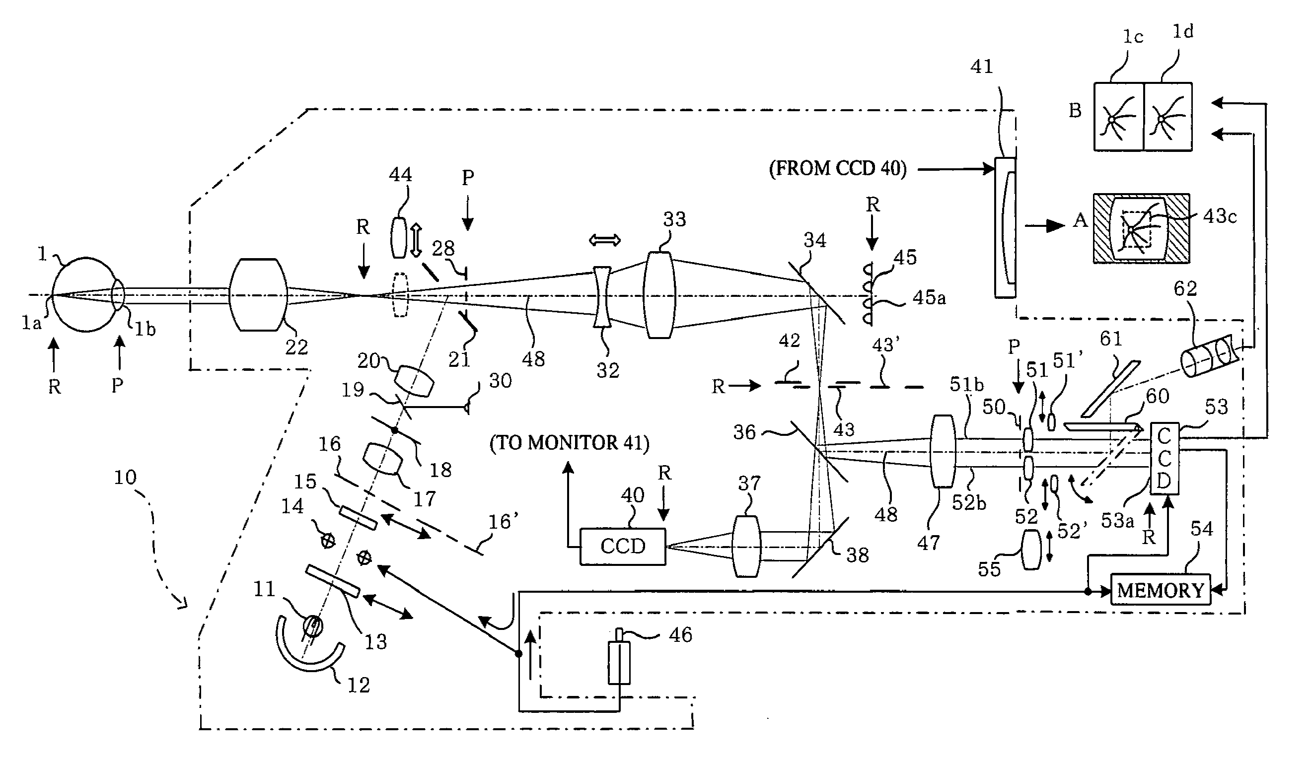
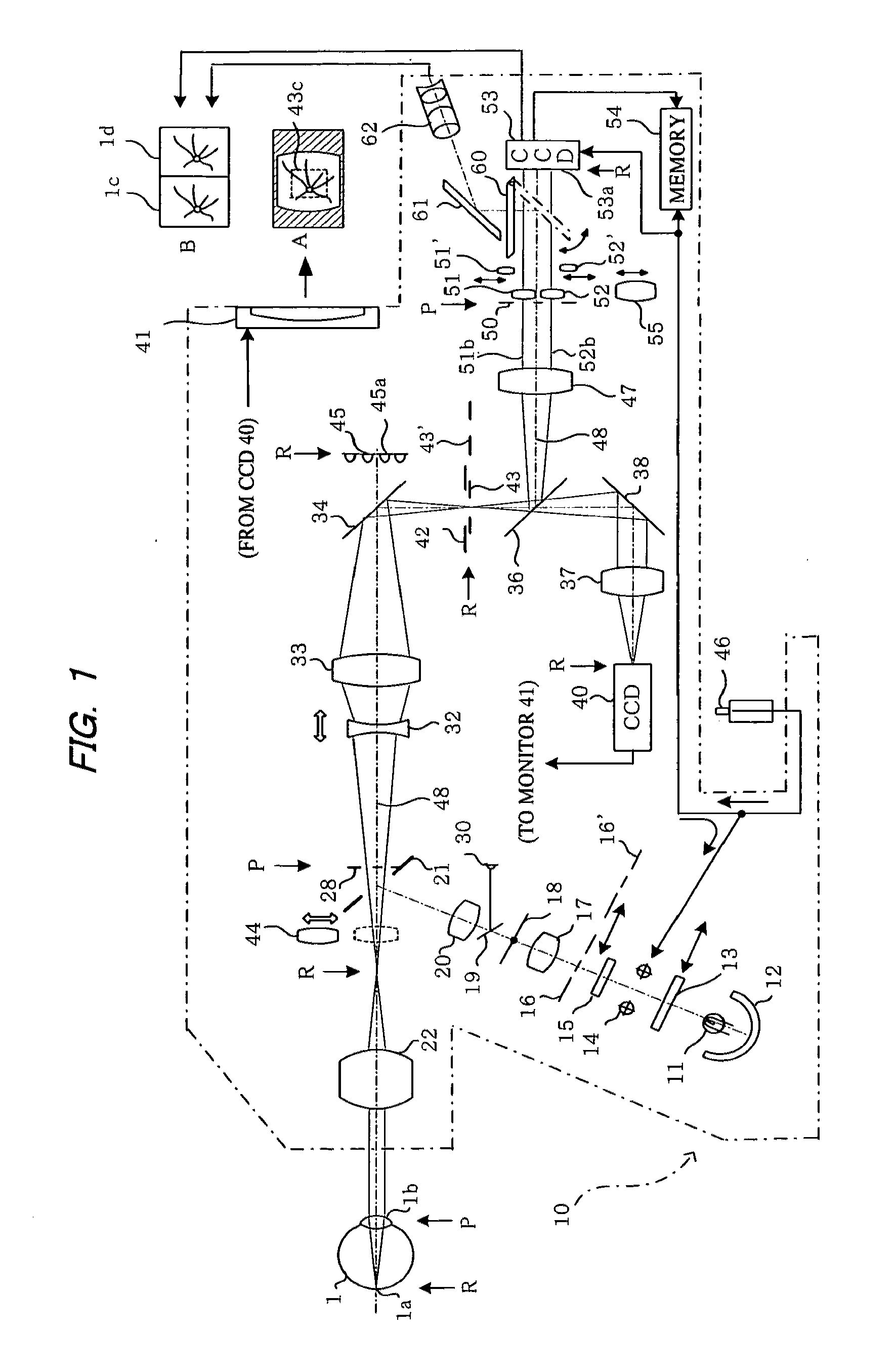
[0033]FIG. 1 shows a fundus camera 10 capable of stereoscopic photography (three-dimensional photography) and monocular photography. The illustration in FIG. 1 is primarily that of stereoscopic photography, and a switchover to each corresponding optical element can be made when monocular photography is performed.

[0034]The fundus camera 10 is provided with an illumination optical system for illuminating the ocular fundus and an optical system for forming an image of the illuminated ocular fundus. In the illumination optical system, light emitted from a light source 11 such as a halogen lamp and light reflected by a concave mirror 12 is converted into infrared light via a visible-blocking / infrared-transmitting filter 13 that can be inserted into and removed from the optical path. The light then passes through a strobe 14 onto a diffusion plate 15 and is diffused thereon to illuminate a ring slit 16 for stereoscopic photography disposed in a position conjugate with an anterior ocular s...

embodiment 2

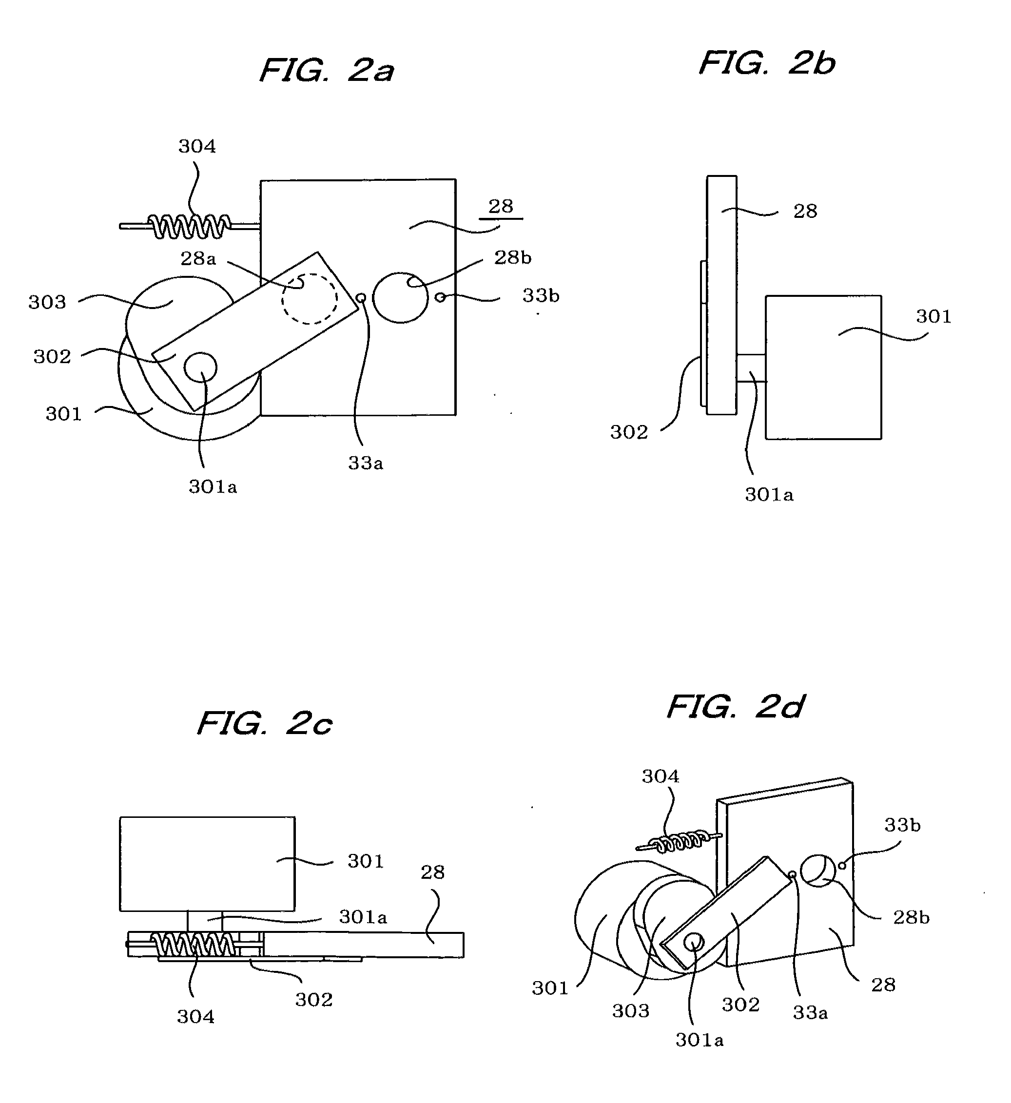
[0087]In the above-mentioned embodiment, the shutter plate 302 is linked to the drive shaft of the rotary solenoid 301 coaxially with the cam plate 303 for moving the stop plate 28. The stop plate 28 is moved so as to intersect the optical axis so that, in monocular photography, the stop plate is positioned in a first position in which one aperture (28b) of the two stop apertures 28a, 28b is disposed substantially at the center of the optical axis (upper right of FIG. 3), and, in stereoscopic photography, it is positioned in a second position in which the two stop apertures 28a, 28b are disposed off-center from the optical axis (lower right of FIG. 3). The shutter plate 302 is operated in accordance with the drive of the rotary solenoid 301 so that the aperture 28a of the two stop apertures 28a, 28b is closed in the first position (upper right of FIG. 3) of the stop plate 28 and so that both of the two stop apertures 28a, 28b are open in the second position (lower right of FIG. 3) o...


PUM


Abstract

Positioning control relating to a two-aperture stop necessary for stereoscopic photography can be performed accurately and securely using a simple, inexpensive, compact, and lightweight structure. The apparatus comprises a two-aperture stop (28) provided with two stop apertures (28a, 28b), and a shutter plate (302) for opening and closing one of the two stop apertures. The two-aperture stop (28) is moved so as to intersect with an optical axis so that in monocular photography the two-aperture stop is positioned in a first position in which the stop aperture (28b) is disposed substantially at the center of the optical axis and so that in stereoscopic photography it is positioned in a second position in which the two stop apertures (28a, 28b) are disposed off-center from the optical axis. A drive mechanism comprising a cam plate (303), a spring (304), and a rotary solenoid (301) is used to move the shutter plate (302) so as to close the stop opening (28a) of the two stop apertures in the first position and to open both of the two stop apertures (28a, 28b) in the second position.

Description

TECHNICAL FIELD[0001]The present invention relates to an ophthalmic photography apparatus for performing stereoscopic photography using two stop apertures that are disposed off-center from an optical axis in a photographic optical system.BACKGROUND ART[0002]Conventionally, as shown in, for example, following Patent Documents 1 through 4, various proposals have been made with respect to an ophthalmic photography apparatus in which a photographic stop formed of a two-aperture stop is disposed in a photographic optical system to perform stereoscopic fundus photography with a different parallax.PRIOR ART DOCUMENTSPatent Documents[0003]Patent Document 1: Japanese Laid-open Patent Publication No. 2008-55010[0004]Patent Document 2: Japanese Examined Patent Publication No. 1987-46170[0005]Patent Document 3: Japanese Laid-open Utility Model Publication No. 1988-68302[0006]Patent Document 4: Japanese Laid-open Patent Publication No. 1998-75932SUMMARY OF INVENTIONProblems to be Solved[0007]The...

Claims


Application Information

Patent Timeline
IPC IPC(8): A61B3/12
CPCG03B35/00A61B3/14
Inventor KAKUUCHI, ATSUSHI
Owner KOWA CO LTD
Why Eureka
Try Eureka