Handlebar grip assembly

a technology for bicycle handles and parts, applied in bicycle equipment, steering devices, transportation and packaging, etc., can solve the problems of easy drop of plugs b>64/b> and still the handlebar grip

Inactive Publication Date: 2012-03-29
WANG JOHN
View PDF7 Cites 262 Cited by
  • Summary
  • Abstract
  • Description
  • Claims
  • Application Information

AI Technical Summary

Benefits of technology

[0015]The present invention will become more obvious from the following description when taken in connection with the accompanyi

Problems solved by technology

However, the handlebar grip still has several disadvan

Method used


Image

  • Handlebar grip assembly
  • Handlebar grip assembly
  • Handlebar grip assembly

Examples


Embodiment Construction

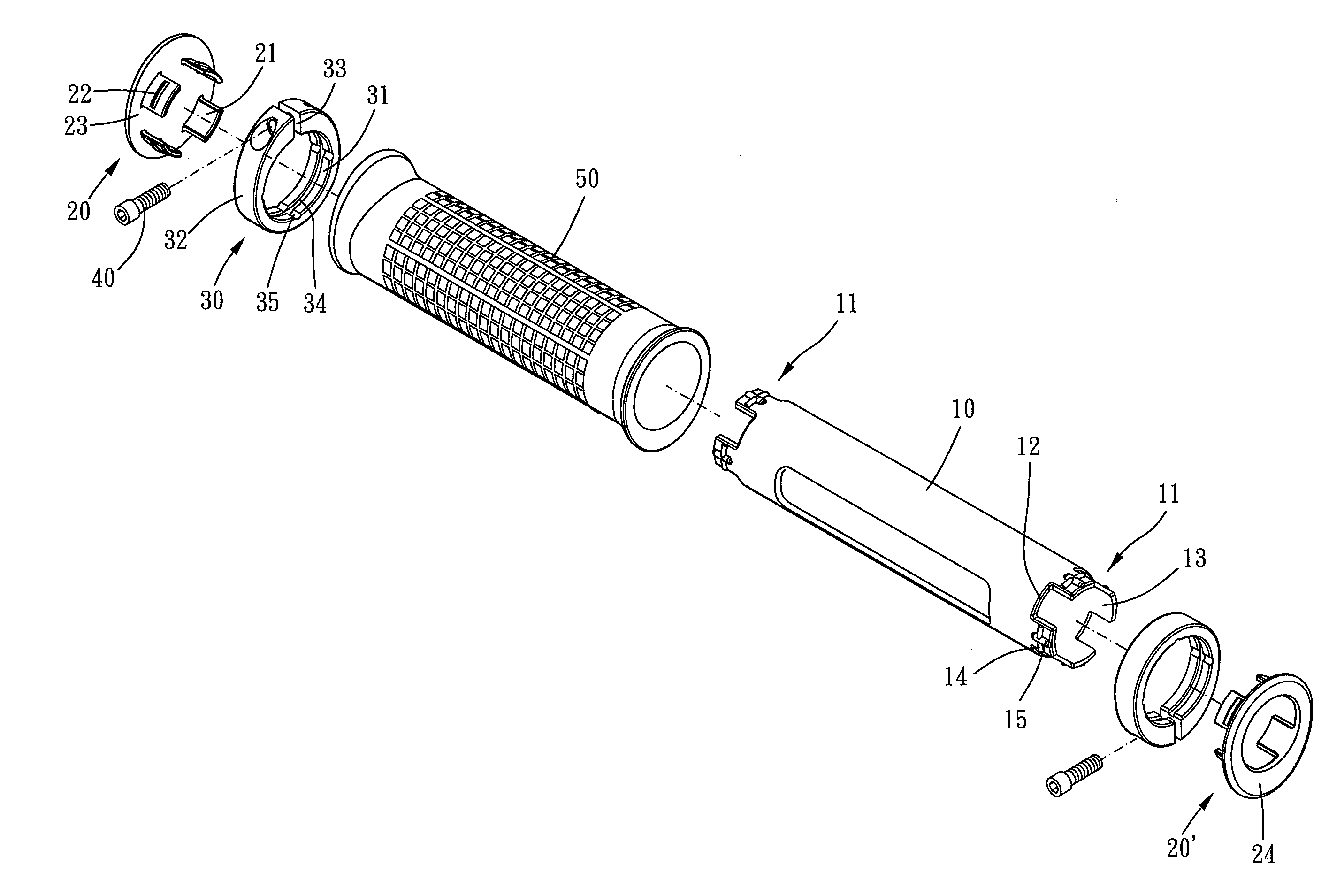
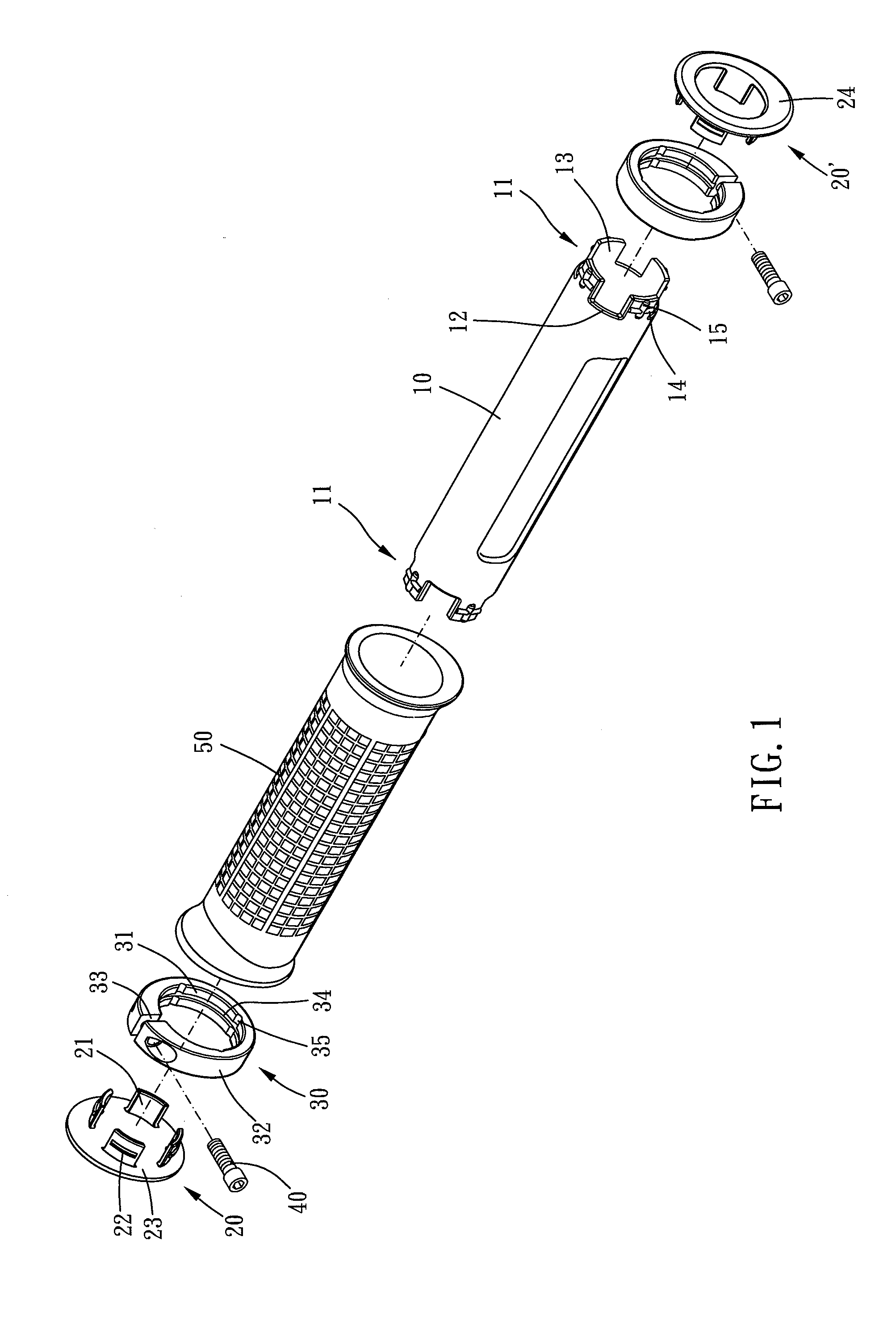
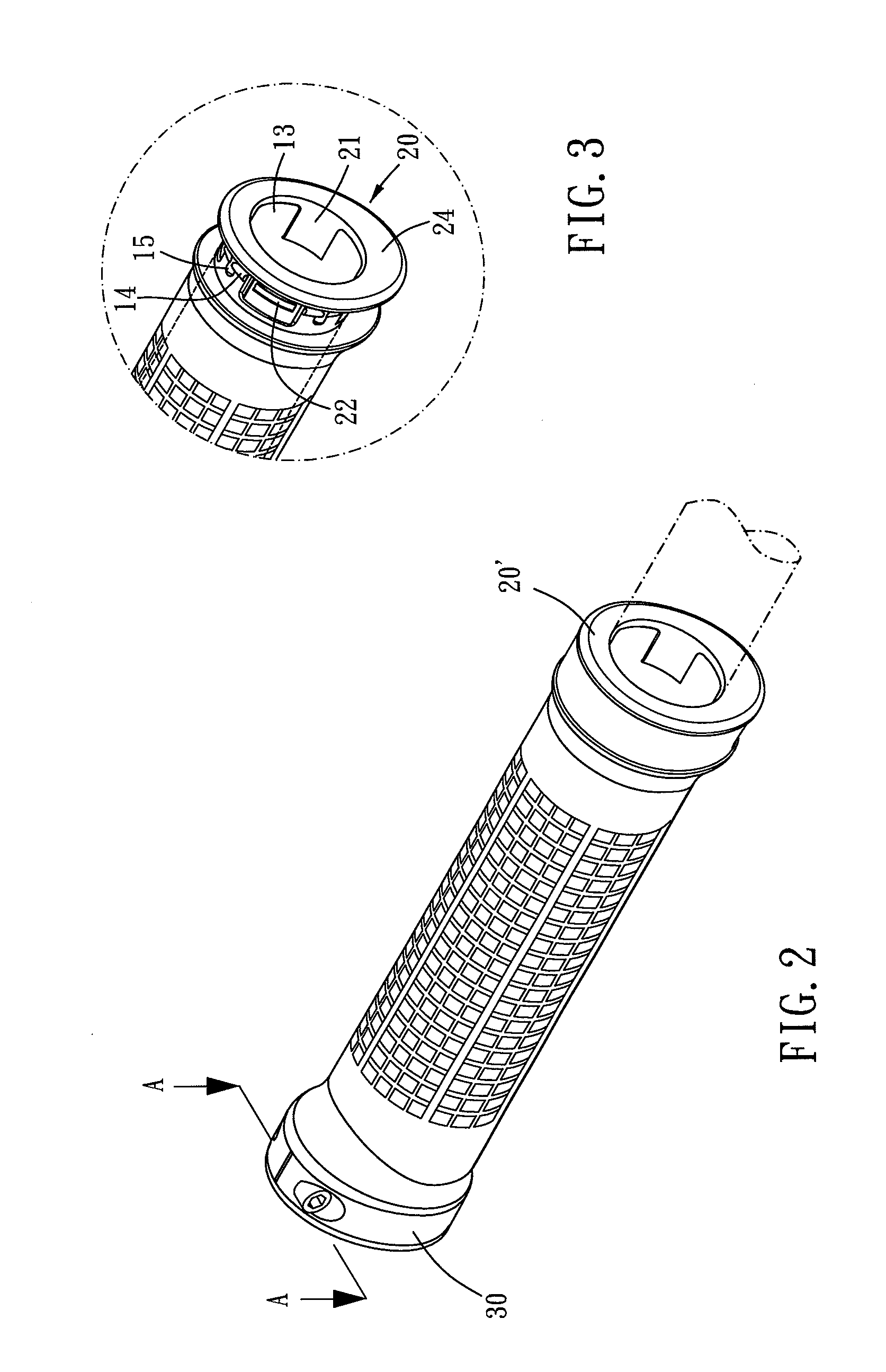
[0022]Please refer to FIG. 1 to FIG. 4 for a preferred embodiment of the present invention. The handlebar grip assembly of the present embodiment includes a sleeve 10, two covers 20, two clamps 30 and a tightening means.

[0023]The sleeve 10 is made of polypropylene. The sleeve 10 is adapted for a handlebar to be received therein. Preferably, a flexible grip 50, which is made of thermoplastic rubber, is covered on outer surface of the sleeve 10. The sleeve 10 has two clamping ends 11. The clamping end 11 is formed with at least two axial grooves 12. A first clamping piece 13 is defined between any two adjacent grooves 12. The first clamping piece 13 is formed with a first lateral rib 14 and an axial rib 15. The first lateral rib 14 and the axial rib 15 are located on an outside surface of the first clamping piece 13 away from the central axis of the sleeve 10. Preferably, each one of the first clamping pieces has a first lateral rib and an axial rib. The first lateral rib 14 crosses t...


PUM


Abstract

A handlebar grip assembly of the present invention includes a sleeve, two covers and two clamps. The sleeve has two clamping ends which defines several axial grooves. A first clamping piece is defined between any two adjacent grooves. The first clamping piece is formed with an axial rib and a first lateral rib which crosses through the axial rib. The cover has several second clamping pieces which is adapted for being inserted in the grooves. The second clamping piece is formed with a second lateral rib. The first lateral ribs and the second lateral ribs are coplanar arranged. The clamp has an inner surface which is formed with an annular recess and several axial recesses. The annular recess is adapted for the first lateral ribs and the second lateral ribs to be received therein. The axial recesses are adapted for the axial ribs to be received therein.

Description

BACKGROUND OF THE INVENTION[0001]1. Field of the Invention[0002]The present invention relates to a handlebar grip of a bicycle.[0003]2. Description of the Prior Art[0004]Conventional handlebar grip has a hard inner tube and a soft outer sleeve. The inner tube is received in and is covered by the outer sleeve, as shown in TW M282905 and U.S. Pat. No. 6,263,759. One end of the inner tube is formed with two protruding pieces. The protruding pieces are received in a clamp. The protruding pieces and the clamp are used to clutch a handlebar of a bicycle. The handlebar is usually scratched by the protruding pieces and the clamp.[0005]Other handlebar grip, as shown in FIG. 6, has an inner tube, an outer sleeve 63, a clamp 65 and a plug 64. The inner tube is provided for a handlebar 61 to be inserted therein. One end of the inner tube is formed with plurality of protruding pieces 62. The protruding pieces 62 are received in the clamp 65. As such, the clamp 65 is divided from the handlebar 61...

Claims


Application Information

Patent Timeline
IPC IPC(8): B62K21/26
CPCY10T74/20828B62K21/26
Inventor WANG, JOHN
Owner WANG JOHN
Why Eureka
Try Eureka