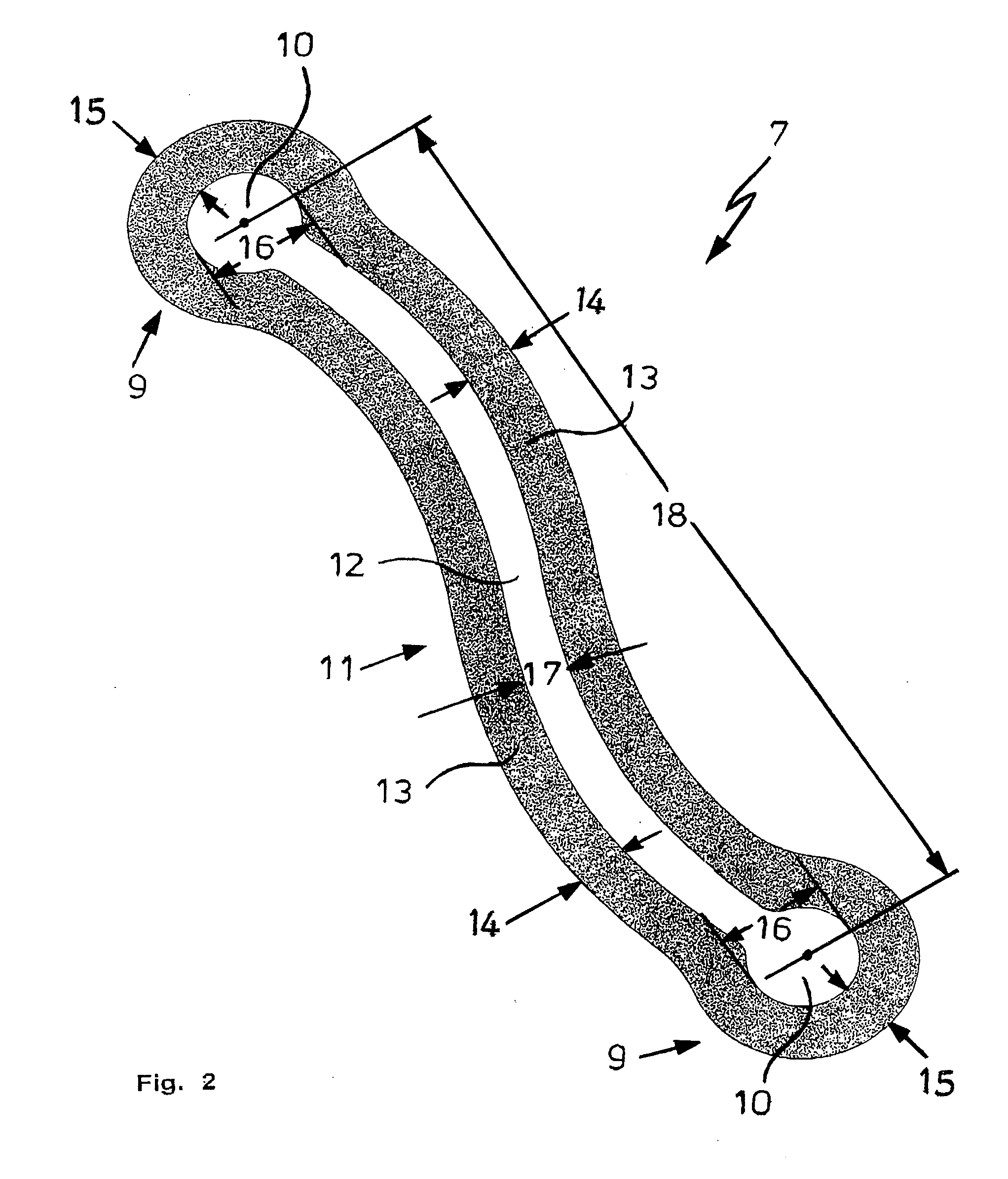
[0014]The form of the curve of the protrusion tie may be chosen at random, as long as it permits an elastic
length change of the center section with a simultaneous width change of the center section. In terms of durability and user comfort of the anti-snoring device, an S-shaped contour proved to be ideal for the center section. In conjunction with an appropriately shaped elongated hole, this results in two S-shaped longitudinal edge strips capable of spring action.
[0016]Preferably, the center section in one embodiment of the invention has at least one elongated hole that is connected on its narrow side with at least one of the round holes of the protrusion tie. As a result, the fixing button connecting the upper jaw bar or the lower jaw bar with the protrusion tie can be moved from the round hole to the elongated hole and vice versa so that the distance between the two fixing buttons holding the protrusion tie can change. This makes it possible for the protrusion tie to act differently during the closing and the opening of the mouth, and that in the open as well as the closed position of the mouth the position of the lower
jar relative to the upper jaw may be different, depending on the length of the elongated hole and the position of the fixing button, and may be influenced within these parameters by the user of the anti-snoring device according to the invention. When a certain pressure force is exerted on the protrusion tie, the fixing buttons unlock automatically from the round holes and slide into the elongated holes until an occurring tensile force moves the fixing buttons in the opposite direction towards the round holes, locking them there. For the user, this significantly increases the comfort of wearing the device.
[0017]The freedom of motion of the connecting fixing button can be determined by the width of the elongated hole relative to the
diameter of the round hole. In a preferred embodiment of the anti-snoring device according to the invention, the width of the elongated hole is smaller than or equal to the
diameter of the round hole. This results in a sliding seat for the fixing button that, in the first case, is impeded by the longitudinal edge strips and / or the longitudinal center strips that can be deflected transversely in their extension direction, but is unimpeded in the second case. Preferably, at the transition from the elongated hole to the round hole, a step or a narrow section is provided that has a snap effect during the movement of the fixing button from the round hole into the elongated hole and vice versa. The snapping of the fixing button out of or into the round hole can be felt by the user of the anti-snoring device and allows the user to influence the movement of the lower jaw to a limited degree.
[0018]The ability of the fixing button to move impeded or unimpeded from its basic position in the round hole to the alternate position in the elongated hole also helps to prevent damage to the protrusion tie caused by excessive
axial pressure forces. In addition, it avoids the
lateral deflection of the protrusion tie away from the upper jaw bar and the lower jaw bar in the direction of the user's
cheek, thereby improving the user's feeling of comfort.
[0019]It proved to be favorable to make the fixing button a single piece. On the one hand, this facilitates the production and the installation of the button, while, on the other hand, ensures a good stability of the button, especially during its movement between the elongated and the round hole. Advantageously, from the inner flank in each case and through the preferably round receptacles of the upper jaw bars or the lower jaw bars, the fixing button can be locked, with minimal axial play and in a manner that makes it difficult to detach, into the round and / or the elongated hole of the protrusion tie whose end sections are in contact with the outer flanks of the bars.
[0020]To summarize briefly, compared with known devices, the new anti-snoring device according to the invention has the significant
advantage of a distinctly improved comfort while in use and, in connection with that, a much higher acceptance that is due to the fact that the hinged connection of the upper and lower shell is engineered to be not completely rigid. Within a given framework, the distance of the points of engagement of the fixing buttons on the protrusion ties is variable and dependent on the force that acts on the protrusion tie in the longitudinal direction and can be influenced by the user him / herself. With a sufficient tensile force, the two protrusion ties are extended elastically, i.e. reversibly, in the longitudinal direction; in case of an excessive pressure force, the fixing buttons unlock from the round holes provided as support points and move into the elongated holes. This usually occurs when, relative to the upper jaw, the lower jaw reaches certain end positions determined by the anti-snoring device with the
mouth closed or open. Due to the simple geometric shape of the protrusion tie and the single-piece design, it is, on the one hand, easier and therefore less expensive to manufacture the proposed anti-snoring device compared with known devices of this type and, on the other hand, it offers a much longer service life than these due to the damped stop of the lower jaw when reaching the end position.

