Motorized Venetian Blind System

Inactive Publication Date: 2012-03-29
LUTRON TECH CO LLC
View PDF14 Cites 77 Cited by
  • Summary
  • Abstract
  • Description
  • Claims
  • Application Information

AI Technical Summary

Problems solved by technology

This can be disadvantageous when, for example, the bottom rail is lowered to a fully-lowered position.

Method used


Image

  • Motorized Venetian Blind System
  • Motorized Venetian Blind System
  • Motorized Venetian Blind System

Examples


first embodiment

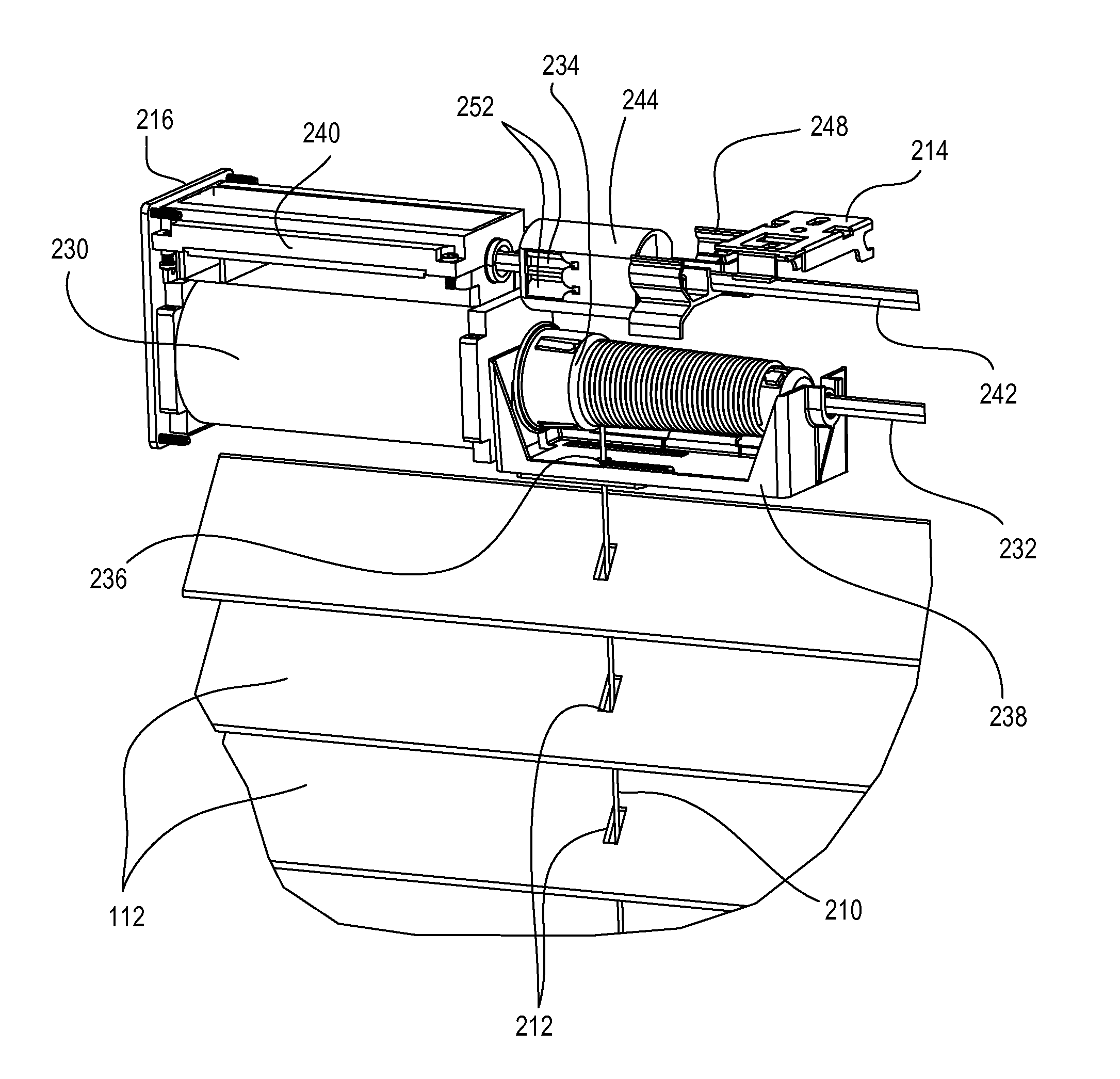
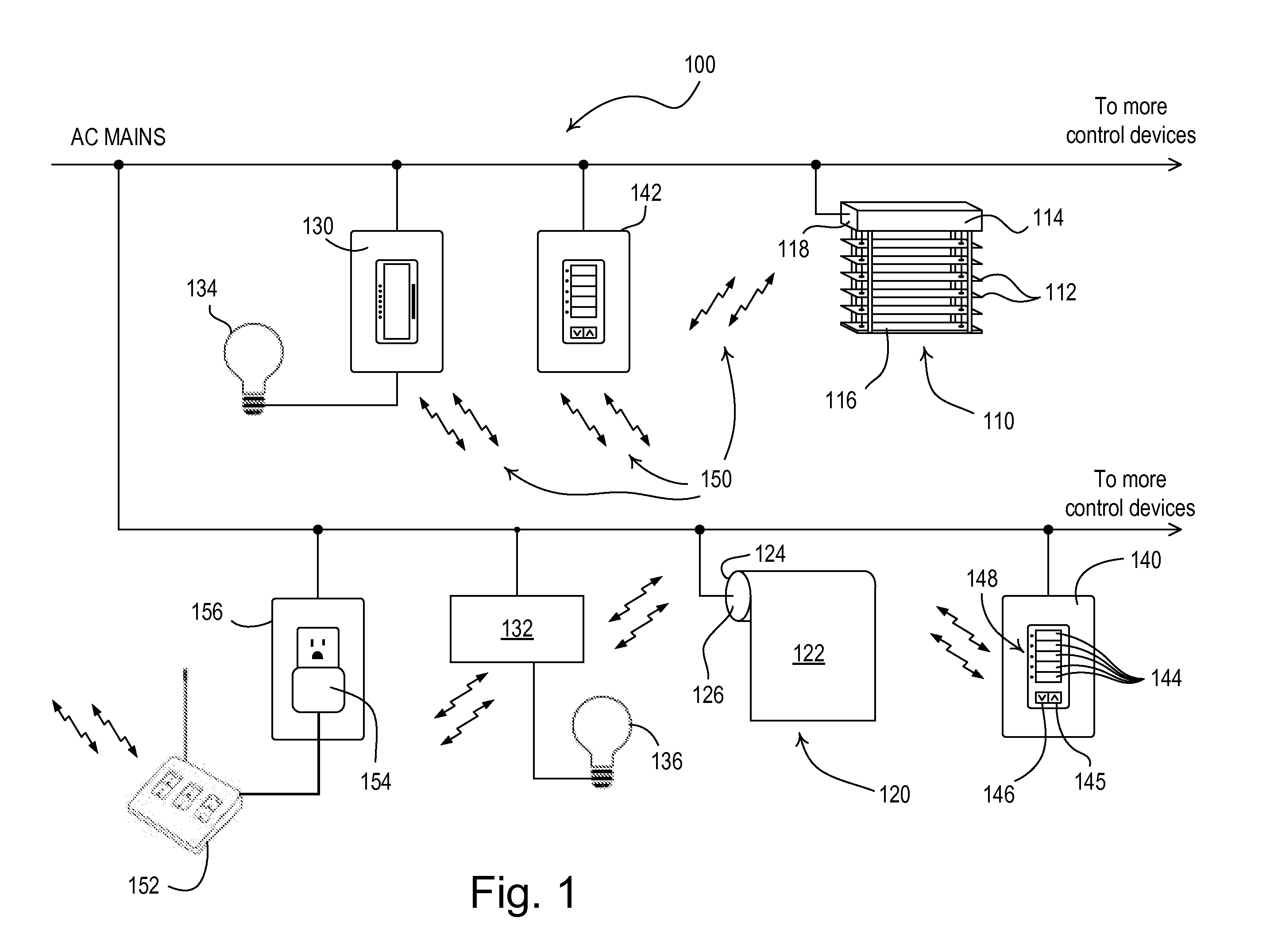
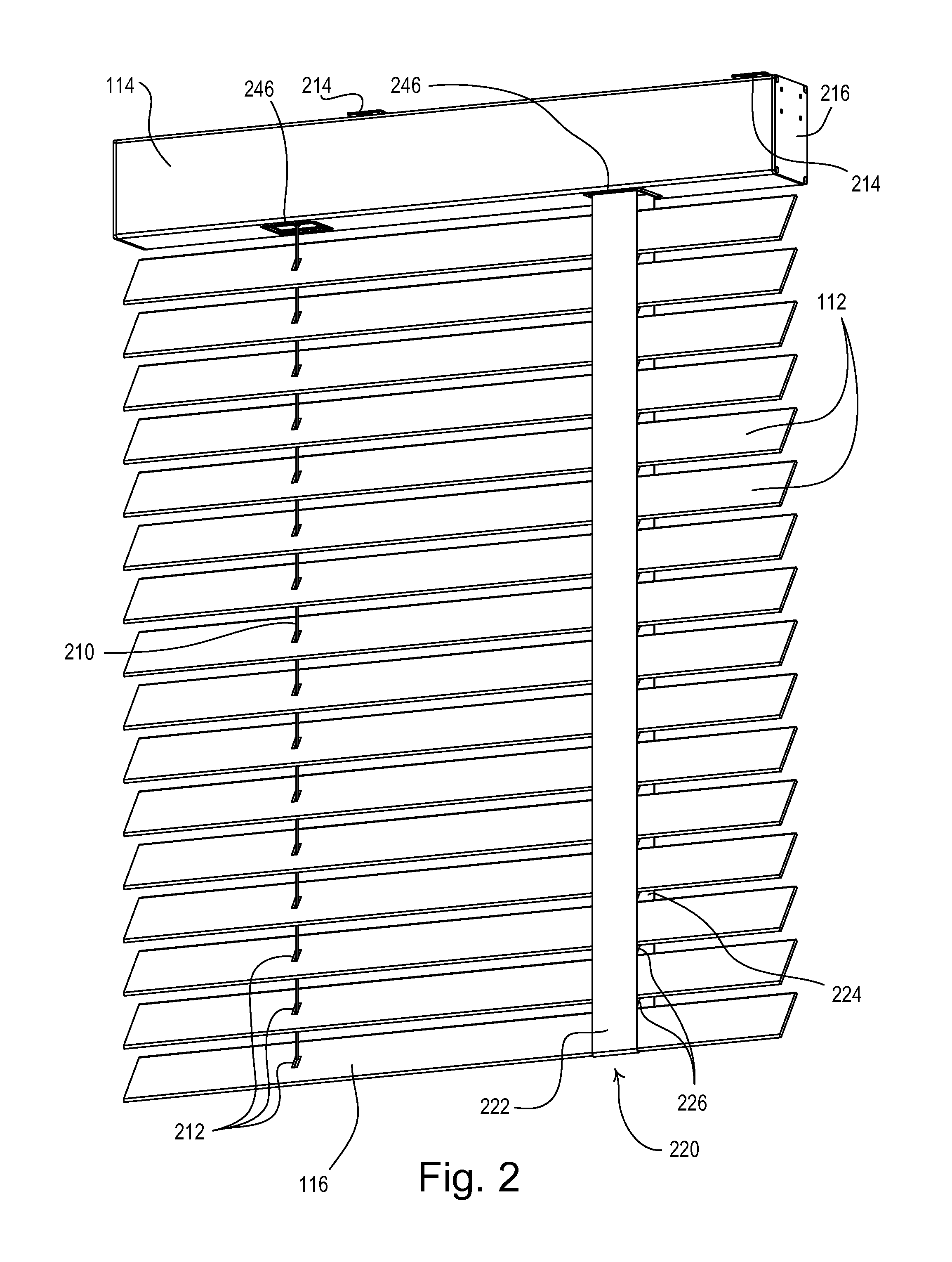
[0039]FIG. 1 is a simplified block diagram of a wireless load control system 100 having a motorized venetian blind system 110 according to the present invention. The blind system 110 comprises a plurality of flat slats 112 displaced between a head rail 114 and a bottom rail 116, and may be mounted in front of a window. The blind system 110 also comprises a blind drive unit 118 located in the head rail 114 for raising and lowering the bottom rail 116, and tilting the slats 112 to control the amount of daylight entering a space as will be described in greater detail below. According to the present invention, the blind drive unit 118 is operable to independently control a position PBLIND of the bottom rail 116 and a tilt angle θBLIND of the slats 112, so as to control the amount of daylight entering the space in which the blind system 110 is installed. The blind drive unit 118 is operable to receive power from a source of AC power (e.g., an AC mains voltage, such as 120 VAC @ 60 Hz). A...

second embodiment

[0069]FIG. 15 is a simplified block diagram of a load control system 600 having multiple venetian blind systems 610 the present invention. The control devices of the load control system 600 are operable to communication with each other via wired communication links as will be described below. The load control system 600 is operable to control the level of illumination in a space by controlling the intensity level of the electrical lights in the space and the daylight entering the space. Specifically, the load control system 600 is operable to control the amount of power delivered to (and thus the intensity of) a plurality of lighting loads, e.g., a plurality of fluorescent lamps 620, and to control the positions PBLIND of the bottom rails 116 and the tilt angles θBLIND of the slats 112 of the motorized blind systems 610, as well as fabric positions of motorized roller shades 630, to thus control the amount of sunlight entering the space. The load control system 600 could comprise o...


PUM


Abstract

A motorized venetian blind system for covering a window of a space comprising a blind drive unit having two motors to provide for independent control of a position of a bottom rail via a lift cord and a tilt angle of a plurality of slats of the blind system. The blind drive unit has a headrail with a side panel and at least one of the motors is between between the side panel and the lift cord. The blind drive unit also has a spring-wrap brake. The blind drive unit is operable to adjust the position of the bottom rail to a preset position, and to adjust the tilt angle of the slats to a preset angle in response to receiving a single digital message (e.g., a preset command).

Description

CROSS-REFERENCE TO RELATED APPLICATIONS [0001]This application is a non-provisional application of commonly-assigned U.S. Provisional Application No. 61 / 384,005, filed Sep. 17, 2010, entitled MOTORIZED VENETIAN BLIND SYSTEM, the entire disclosure of which is hereby incorporated by reference.BACKGROUND OF THE INVENTION[0002]1. Field of the Invention[0003]The present invention relates to a window treatments, and more particularly, to a motorized venetian blind system.[0004]2. Description of the Related Art[0005]Window treatments, such as, for example, roller shades, draperies, roman shades, and venetian blinds, are normally mounted in front of windows to provide for control of the amount of sunlight entering a space. A typical venetian blind system comprises a number of elongated slats extending along the width of the window and spaced apart vertically between a head rail and a bottom rail. The blind system typically comprises a lift cord that extends from the bottom rail through open...

Claims


Application Information

Patent Timeline
Patent Type & Authority Applications(United States)
IPC IPC(8): E06B9/322A47H23/04E06B9/68A47H5/02
CPCE06B9/304E06B2009/905E06B9/322
Inventor HONTZ, MATTHEW R.KIRBY, DAVID A.
Owner LUTRON TECH CO LLC
Why Eureka
Try Eureka