
Headrail with reversible cord lock position

a headrail and lock position technology, applied in the field of headrails, can solve the problems of not being able to reverse, reconfiguring the blinds in the shop, increasing the cost of the sale to both the manufacturer and the installer, and achieve the effect of easy removal and easy switching

Inactive Publication Date: 2005-05-31
ITA
View PDF9 Cites 31 Cited by
  • Summary
  • Abstract
  • Description
  • Claims
  • Application Information

AI Technical Summary

Benefits of technology

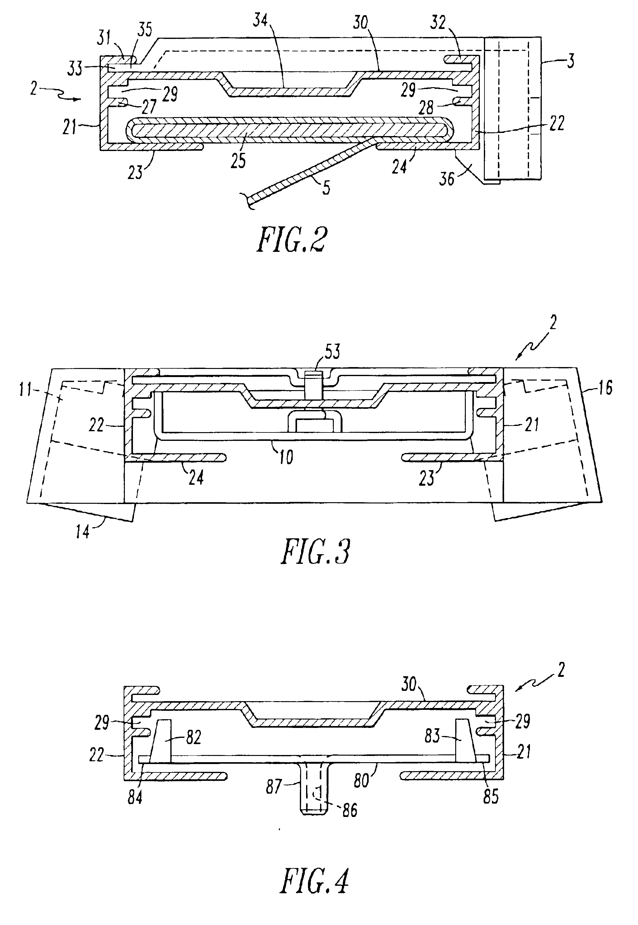
[0007]I provide a headrail for venetian type blinds and pleated shades in which the cord lock can be easily switched form the right side of the blind to the left side of the blind or vice versa. The headrail has an elongated body having a base, a first sidewall and a second sidewall. The first and second sidewalls are spaced apart, generally parallel and attached to the base. At least one channel or rib is provided on the inside surface of each sidewall. Preferably the rib or channel extends the full length of the blind. However, the rib or channel need only be at the ends of the headrail. I provide an insert or endcap that fits into the end of the headrail and is carried by the slot or rib on the sidewalls. A pair of pockets are provided on the insert, the pockets being positioned so that one pocket is adjacent each sidewall when the insert is attached to the end of a headrail. The pockets are sized and configured to receive a cord lock such that the cord lock can be easily removed from one pocket and placed in the other pocket by an installer.

Problems solved by technology

Such inserts are designed to fit into either the left end or right end of the headrail and are not reversible.
Although some installers have the skills and the tools to fabricate blinds in their shop they seldom reconfigure blinds in their shop to change the position of the controls because that is a time consuming process.
Each return means that the installer must make a second trip to the home or business thereby increasing the cost of the sale to both the manufacturer and the installer.
Furthermore, if an installer is required to return to a home to replace a blind, very often the customer will ask the installer to make other changes or adjustments.

Method used


Image

  • Headrail with reversible cord lock position
  • Headrail with reversible cord lock position
  • Headrail with reversible cord lock position

Examples


Embodiment Construction

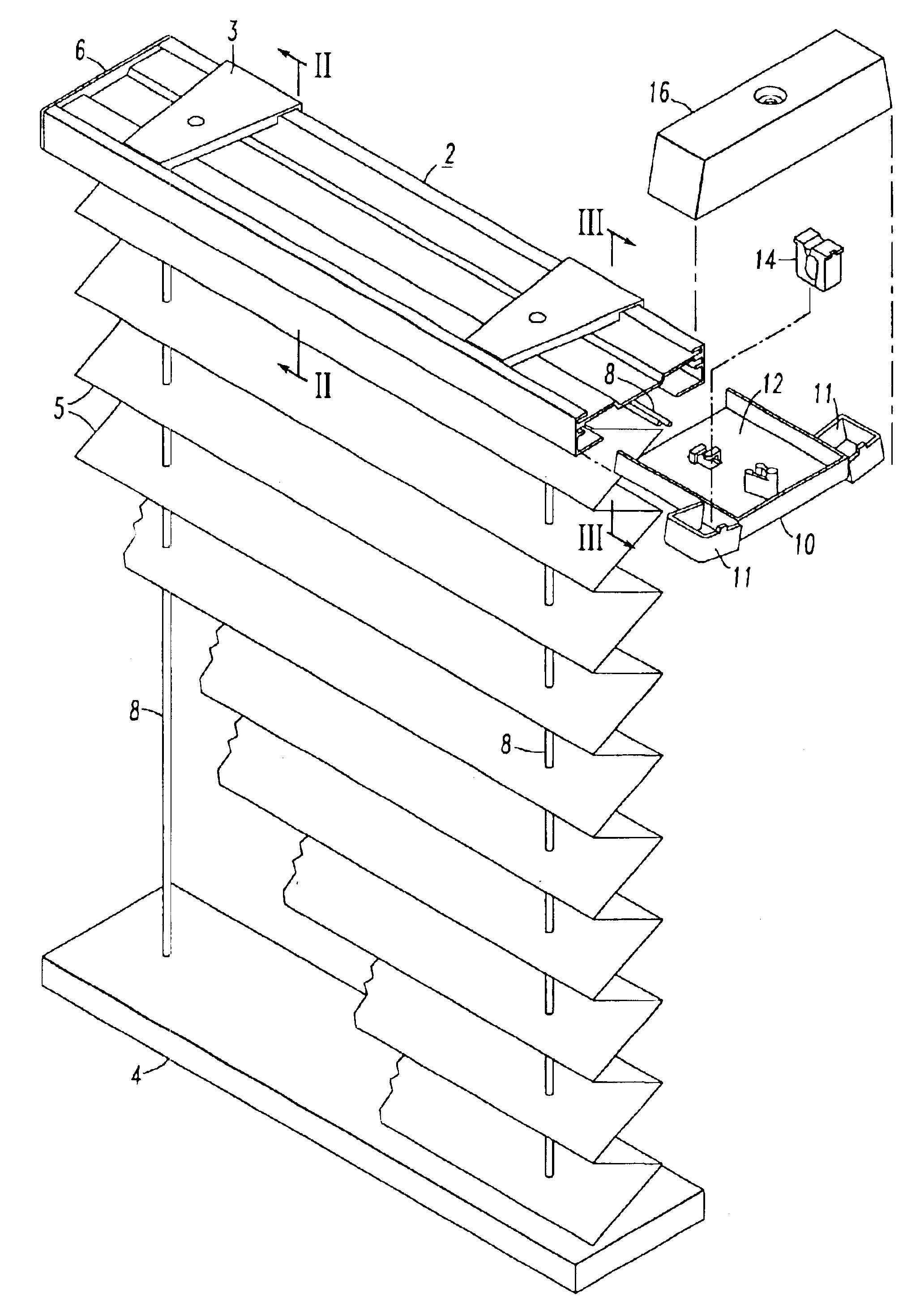
[0025]As shown in FIG. 1 a window covering which utilizes the headrail and insert of the present invention is comprised of an elongated body or headrail 2, a bottomrail 4 and a pleated window covering material 5 extending therebetween. Although the embodiment shown in FIG. 1 is a pleated shade the present invention can be used with any window covering that contains a headrail and lift cords including cellular shades, roman shades and venetian blinds. End cap 6 is attached to one end of the headrail 2. Lift cords 8 pass from the bottomrail 4 into and through the headrail 2. The lift cords 8 may pass through holes in the window covering material 5 or be routed behind the window covering material. Within the headrail the lift cords 8 run to a cord lock 14. They pass through the cord lock 14 and are of a length that an operator of the blind can easily reach the end of the lift cords. The number of lift cords that are used will vary according to the size of the blind and the cording arra...


PUM


Abstract

A headrail for a venetian type blind or pleated shade has an insert that carries a cord lock. The insert fits into the end of the headrail and is carried by a slot or rib on the sidewalls of the headrail. A pair of pockets are provided on the insert. The pockets are positioned so that one pocket is adjacent each sidewall when the insert is attached to the end of a headrail. The pockets are sized and configured to receive a cord lock such that the cord lock can be easily removed from one pocket and placed in the other pocket by an installer. The pockets preferably are oriented so that a cord passing through the cord lock will run along a path that is not parallel to the sidewalls but is at an angle of about 10°.

Description

FIELD OF INVENTION[0001]The invention relates to headrails for venetian type blinds as well as headrails for pleated shades in which lift cords pass through a cord lock at one end of the headrail.BACKGROUND OF THE INVENTION[0002]Venetian type blinds, pleated shades, roman shades and roll-up blinds have lift cords for raising and lowering the window covering material. The lift cords extend from a bottomrail through or past the window covering material and into the headrail. The cords can be collected on a cord collector within the headrail or, more typically, exit one end of the headrail. In most of these blinds a cord lock is provided at one end of the headrail and the lift cords pass through that cord lock as they exit the headrail. The cord lock allows the user to maintain the blind in any desired position from fully raised to fully lowered.[0003]It is common in the art to provide the tilt cords at one end of the headrail and the lift cords at the opposite end of the headrail as i...

Claims


Application Information

Patent Timeline
Patent Type & Authority Patents(United States)
IPC IPC(8): E06B9/324E06B9/28E06B9/323
CPCE06B9/323E06B9/324Y10S160/902
Inventor TYNER, JAMES D.
Owner ITA
Learn More