Microgrid imaging polarimeters with frequency domain reconstruction

a microgrid and frequency domain technology, applied in the field of imaging polarimeters, can solve the problems of slow acquisition of multiple polarizer measurements for each image pixel, bulky and expensive, and many of the same difficulties of polarimetry,

Active Publication Date: 2012-03-29
THE ARIZONA BOARD OF REGENTS ON BEHALF OF THE UNIV OF ARIZONA
View PDF7 Cites 86 Cited by
  • Summary
  • Abstract
  • Description
  • Claims
  • Application Information

AI Technical Summary

Benefits of technology

[0011]In other examples, methods comprise receiving a stored image associated with a polarizer array that is configured to apply a periodic polarization-dependent intensity modulation to a received irradiance distribution. In the analysis, the stored image is spatially Fourier transformed, and at least one spatial frequency domain filter is applied to the Fourier transformed image. The filtered Fourier transformed image is demodulated, inverse Fourier transformed, and a polarization image associated with at least one of a degree of linear polarization, a degree of circular polarization, an angle of polarization, a degree of polarization, a Stokes parameter s0, a Stokes parameter s1, a Stokes parameter s2, or a Stokes parameter s3 is produced based on the inverse transform. In some examples, the filter is a low pass filter and the polarization image is associated with the Stokes parameter a combination of one or more of the Stokes parameters. In one example, the polarization image is associated with s0. In other examples, the filter is a high pass filter, and the polarization image is associated with a combination of one or

Problems solved by technology

Polarimeters commonly incorporate motors and/or beamsplitters, and tend to be bulky and expensive.
Imaging polarimetry faces the many of the same difficulties as non-imaging polarimetry as well as additional problems.
For example, the acquisition of multiple polarizer measurements for each i

Method used


Image

  • Microgrid imaging polarimeters with frequency domain reconstruction
  • Microgrid imaging polarimeters with frequency domain reconstruction
  • Microgrid imaging polarimeters with frequency domain reconstruction

Examples


Embodiment Construction

[0025]As used in this application and in the claims, the singular forms “a,”“an,” and “the” include the plural forms unless the context clearly dictates otherwise. Additionally, the term “includes” means “comprises.” Further, the term “coupled” does not exclude the presence of intermediate elements between the coupled items.

[0026]The systems, apparatus, and methods described herein should not be construed as limiting in any way. Instead, the present disclosure is directed toward all novel and non-obvious features and aspects of the various disclosed embodiments, alone and in various combinations and sub-combinations with one another. The disclosed systems, methods, and apparatus are not limited to any specific aspect or feature or combinations thereof, nor do the disclosed systems, methods, and apparatus require that any one or more specific advantages be present or problems be solved. Any theories of operation are to facilitate explanation, but the disclosed systems, methods, and a...


PUM


Abstract

A polarization camera includes a microlement polarizer that is situated in proximity to a focal plane array. The microlement polarizer is selectively scanned with respect to an optical image direct to the focal plane array, and an image processor stores a set of images associated with the scanning. Based on the stored images, a polarization image can be produced and displayed. A periodic microelement polarizer modulates the individual images of the set, and these images can be processed by filtering in the spatial frequency domain to isolate contributions associated with one or a combination of Stokes parameters. After filtering, Stokes parameter based images can be obtained by demodulating and inverse Fourier transforming the filtered frequency domain data.

Description

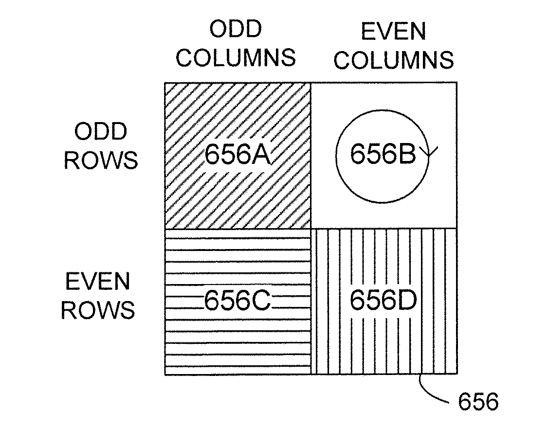
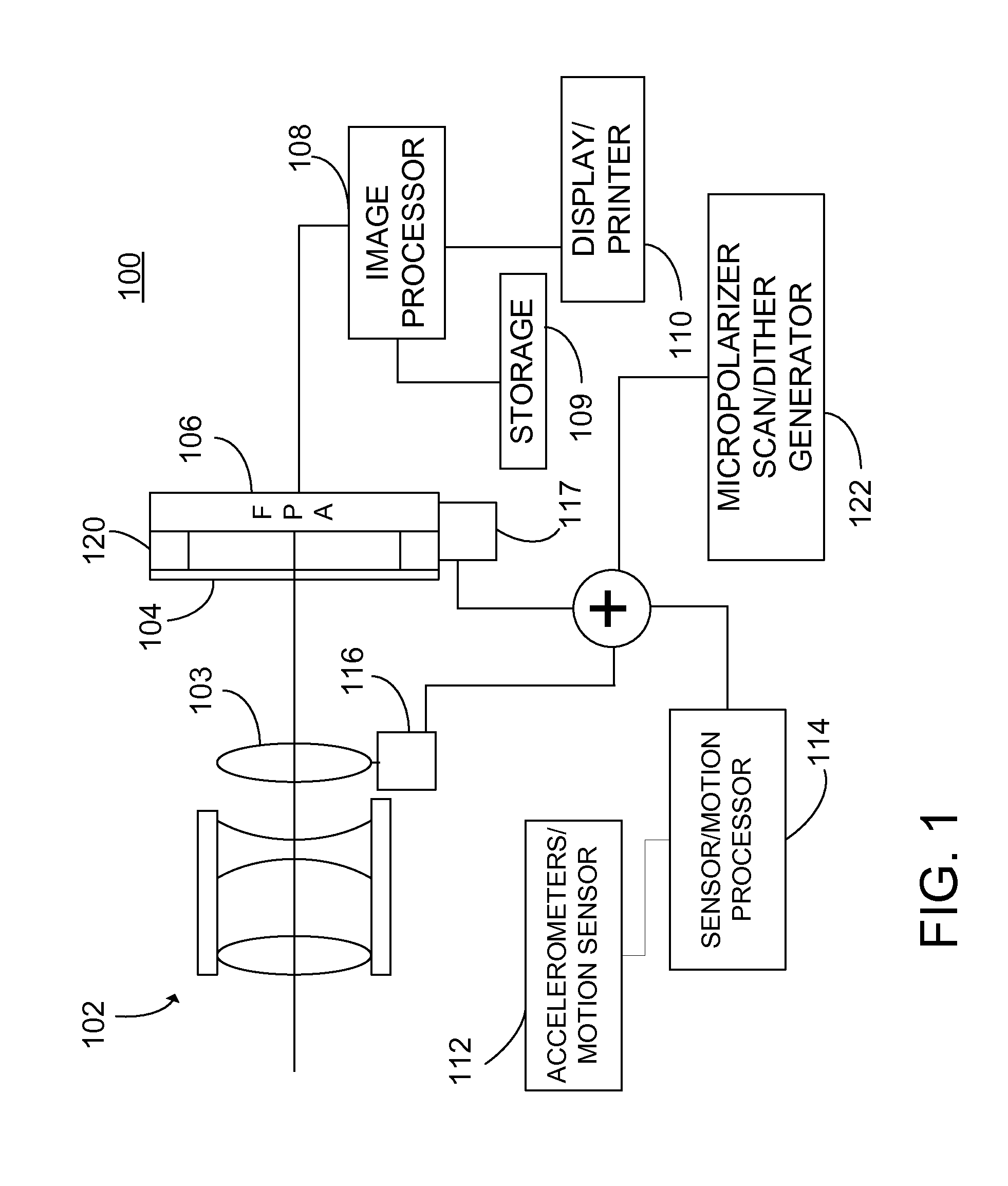
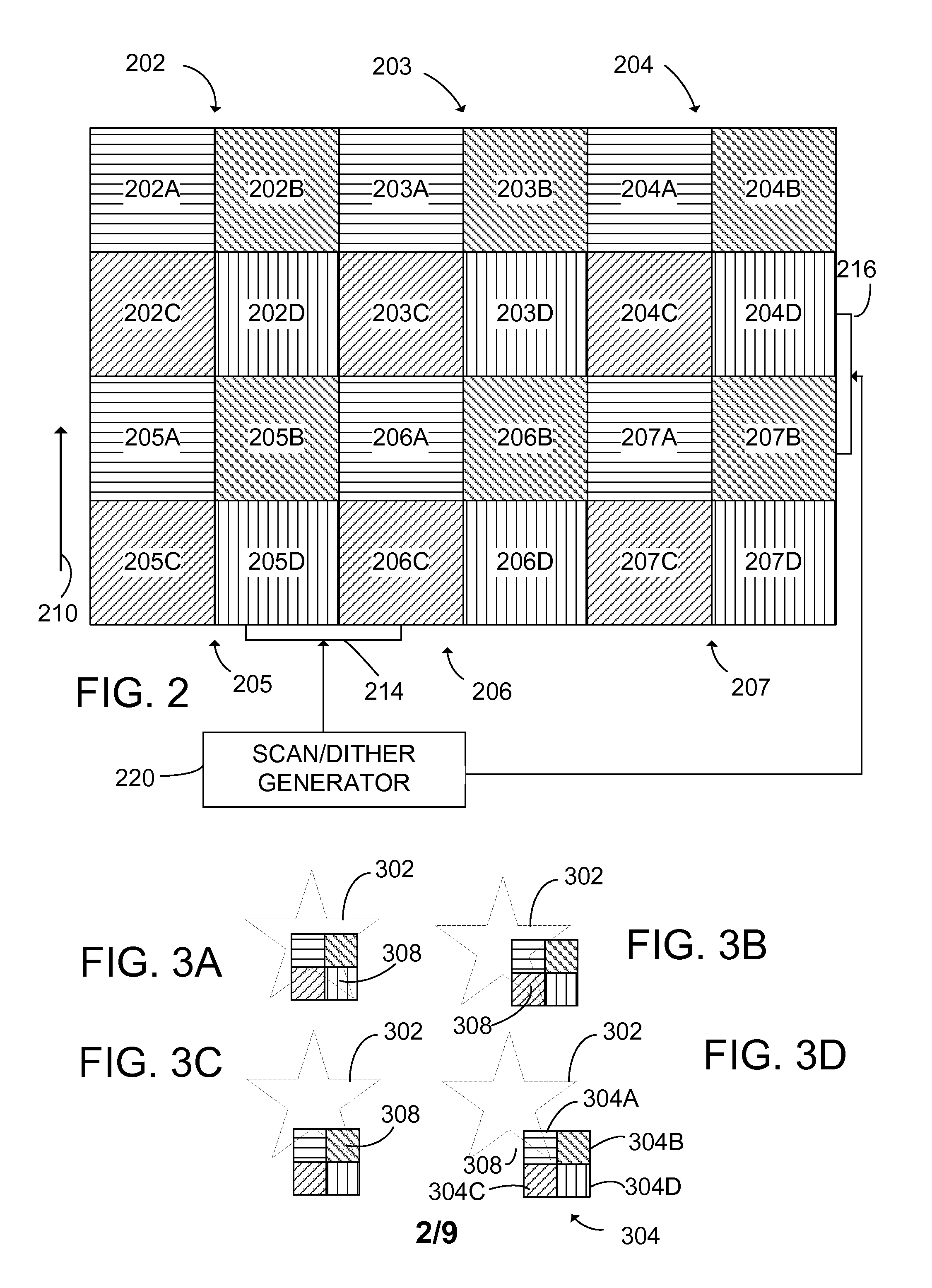
CROSS-REFERENCE TO RELATED APPLICATIONS[0001]This application claims the benefit of U.S. Provisional Applications 61 / 278,352, filed Oct. 6, 2009 and 61 / 268,309, filed Jun. 11, 2009, both of which are incorporated herein by reference.STATEMENT REGARDING GOVERNMENT RIGHTS[0002]This invention was made with government support under Awards FA9550-07-1-0087 and FA9550-08-1-0295 awarded by the U.S. Air Force Office of Scientific Research. The government has certain rights in the invention.FIELD[0003]The disclosure pertains to imaging polarimetry.BACKGROUND[0004]The evaluation of the state of polarization of light received from an object has many applications. For example, polarization based analysis provides information on the orientation in space of chemical bonds, surface orientation, refractive index, texture (including orientation of surface texture), and roughness. Polarization can be used in applications such as the visualization of mechanical stresses and the evaluation of products ...

Claims


Application Information

Patent Timeline
IPC IPC(8): H04N5/335
CPCG01J4/04
Inventor CHIPMAN, RUSSELL A.PAU, STANLEYTYO, J. SCOTTRATLIFF, BRADLEY M.
Owner THE ARIZONA BOARD OF REGENTS ON BEHALF OF THE UNIV OF ARIZONA
Why Eureka
Try Eureka