
Decorative arm sleeves for eyeglasses

a technology of eyeglasses and arm sleeves, applied in the field of eyeglasses and sunglasses, can solve the problems of inability to readily interchange decorative designs in or inability to cost-effectively, durable, or convenient use, and the temple pieces are not proportioned for easy removal or re-attachment to the extension elements of the eyeglass fram

Inactive Publication Date: 2012-03-29
SILVER GLOBAL MFG
View PDF6 Cites 48 Cited by
  • Summary
  • Abstract
  • Description
  • Claims
  • Application Information

AI Technical Summary

Benefits of technology

[0012]It is therefore an object of this invention to provide a system for decorating a temple piece of an eyeglass frame and providing a sturdy and removably engaging affixed of the decorative portion to the temple piece of an eyeglass frame system.

Problems solved by technology

For various reasons, the structures taught therein are not cost-effective, durable, or convenient to use.
However, such temple pieces are not proportioned for ease of removal from or re-attachment to the extension elements of the eyeglass frame.
One disadvantage of these prior art eyeglass frames is the inability to readily interchange decorative designs in or of the temple frames.

Method used


Image

  • Decorative arm sleeves for eyeglasses
  • Decorative arm sleeves for eyeglasses
  • Decorative arm sleeves for eyeglasses

Examples


first embodiment

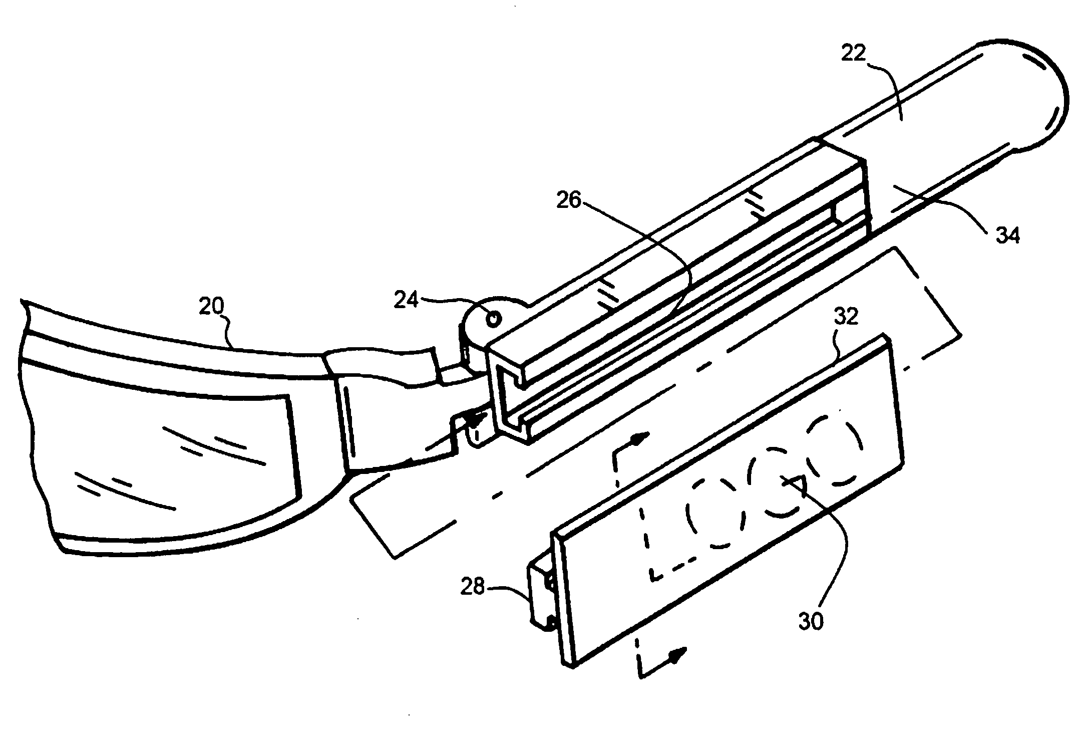
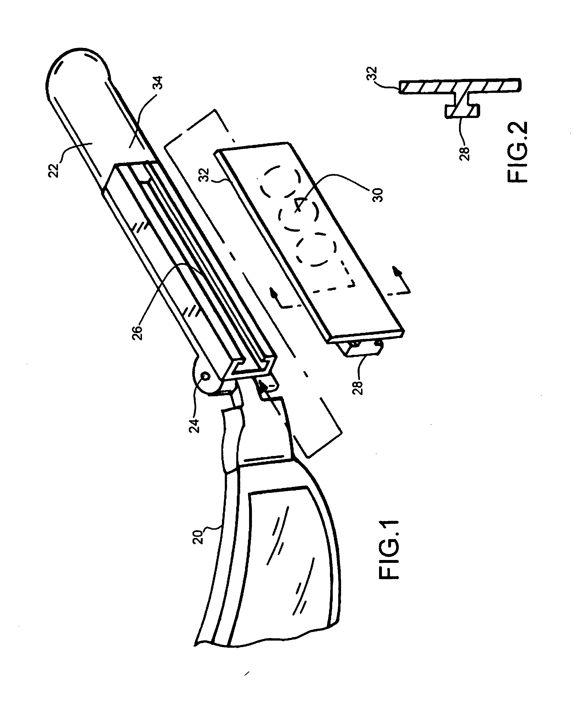
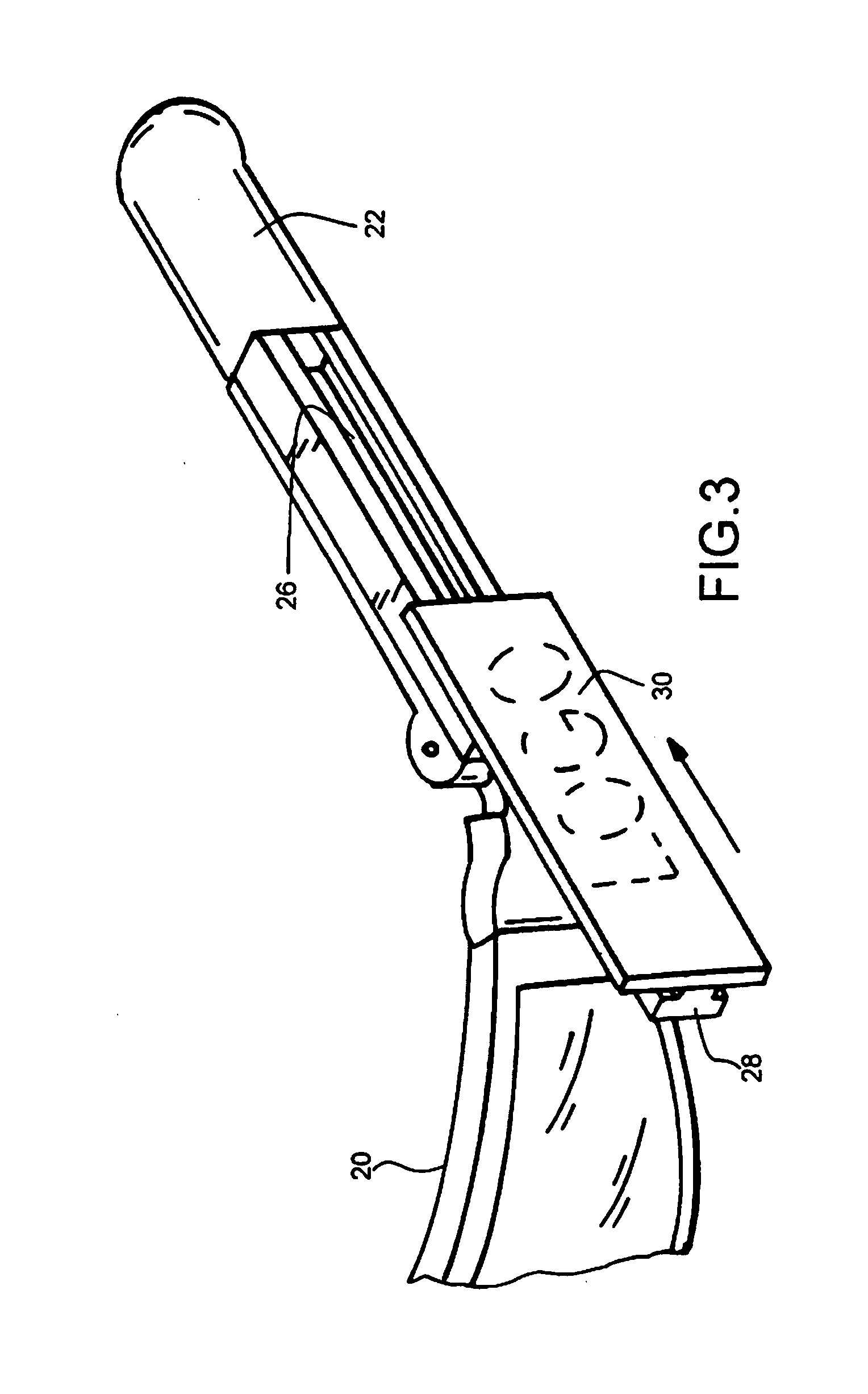
[0032]With reference to the exploded view of FIG. 1, the invention may be seen to include an eyeglass frame 20 and a temple piece 22 which is pivotably connected to the eyeglass frame at a rotational axis 24. As may be appreciated from the geometry of temple frame 22, a portion thereof is provided with a C-shaped channel 26 which acts as a guide or track within which a complemental longitudinal male element 28 of ornamental element 30 may be placed through an opening 31. Said ornamental element is shown in cross-sectional view in FIG. 2. Therefrom, it may be appreciated that male element 28 is proportioned for slidable insertion into C-shaped track 26 of the temple frame 22 while, upon the outer surface of the ornamental element 30 may be provided a logo 32 or any other graphic pattern or icon of interest to the user.

[0033]In FIG. 3 is shown a partial insertion of ornamental element 30 into channel 26 of the temple piece 22 and, in FIG. 4 is shown the complete insertion thereinto. T...

second embodiment

[0034]In FIG. 5 is shown the invention in which ornamental insert 130 differs slightly in cross-section from the geometry of ornamental insert 30 of the embodiment FIGS. 1 through 4. Therein (see FIGS. 5-6) ornamental insert 130 may also be slipped through female opening 131 and into a substantially C-shaped track 126. However, as may be appreciated from the views of FIGS. 8 and 10, the geometry of the ornamental insert differs from the geometry of insert 30 above described, the principal difference being the narrower profile thereof which, it is believed, would be preferred by older users of the instant system in which manual dexterity of the user were not an issue. The system of FIGS. 1-4 would therefore typically be preferred by younger or child-age users than that of the embodiments of FIGS. 5-10.

[0035]Further shown in FIGS. 5 and 6 is recess 127 at the earpiece end of channel 126, and which is proportioned or snap-fit axial engagement with end 133 of element 130 after said elem...


PUM


Abstract

An eyeglass frame system includes a lens frame, a planar side extension pivotally attached at opposite ends of the lens frame, and an integrated earpiece and temple frame, an end opposite to the earpiece portion including an elongate longitudinal channel complemental in cross-sectional geometry to that of the planar side pivotally attached to the lens frame. The temple and earpiece frame may be selectably inserted over the side extension.

Description

BACKGROUND OF THE INVENTION[0001]The present invention relates generally to the field of eyeglasses and sunglasses worn for recreational and other activities. More particularly, this invention pertains to foldable eyeglass frames having selectable decorative ornamentation displayed on the temple pieces of the frame.[0002]It is known in the prior art to embellish such eyeglass frames by providing decorative elements on the side pieces, such side pieces herein termed temple frames. It is also known in the art to select eyeglass frames according to their decorative elements so as to match the graphics of apparel worn by the user or of particular interests to the user.[0003]As examples, U.S. Pat. No. 6,652,093 and PCT Publications WO 98 / 23994, WO 97 / 44699 and WO 09 / 052,705 each describe an eyeglass frame structure comprising a decorative element of a temple frame that is mounted in a manner such that the decorative element can rotate or slide with respect to fixed parts of the temple fr...

Claims


Application Information

Patent Timeline
IPC IPC(8): G02C11/02
CPCG02C11/02
Inventor SILVER, MAX
Owner SILVER GLOBAL MFG
Learn More