Custom eyeglass manufacturing method

a manufacturing method and eyeglass technology, applied in the field of custom eyeglass manufacturing methods, can solve the problems of new manufacturing challenges, and the current eyeglass manufacturing technology does not provide lenses that precisely correct the wavefront aberration of patients

Inactive Publication Date: 2004-01-27
ESSILOR INT CIE GEN DOPTIQUE +1
View PDF61 Cites 196 Cited by
  • Summary
  • Abstract
  • Description
  • Claims
  • Application Information

AI Technical Summary

Benefits of technology

In order to help the computer program find some of the areas automatically, pre-formed or custom-made moldings with or without integrated registration markers could be used with this system. In the simplest form, the patient would wear an existing eyeglass frame of known dimensions, which might have registration marks attached to it. The registration marks could be affixed anywhere on the frame, however, locations behind and in front of the ears, and near the nose might be effective.

Problems solved by technology

Current eyeglass manufacturing technology does not provide lenses that precisely correct a patient's wavefront aberrations.
However, new manufacturing techniques that make use of epoxies, cured to different indexes of refraction matching the wavefront aberrations of a patient, present new manufacturing challenges.

Method used


Image

  • Custom eyeglass manufacturing method
  • Custom eyeglass manufacturing method
  • Custom eyeglass manufacturing method

Examples


Embodiment Construction

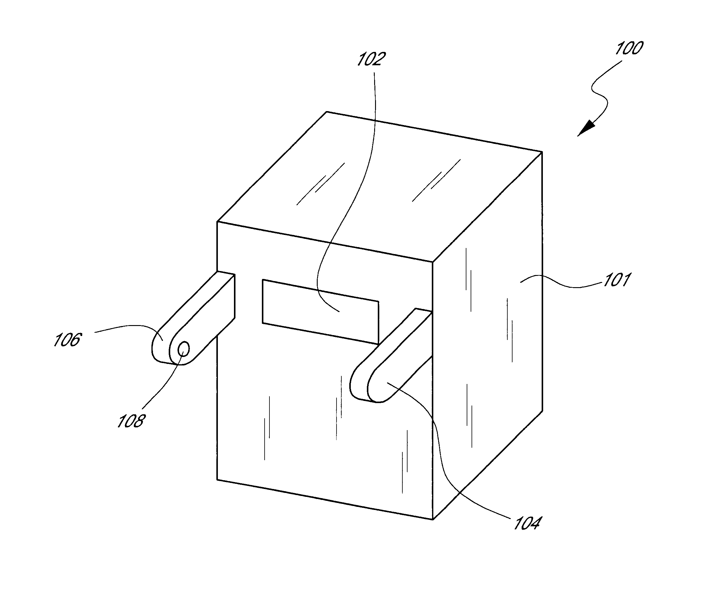
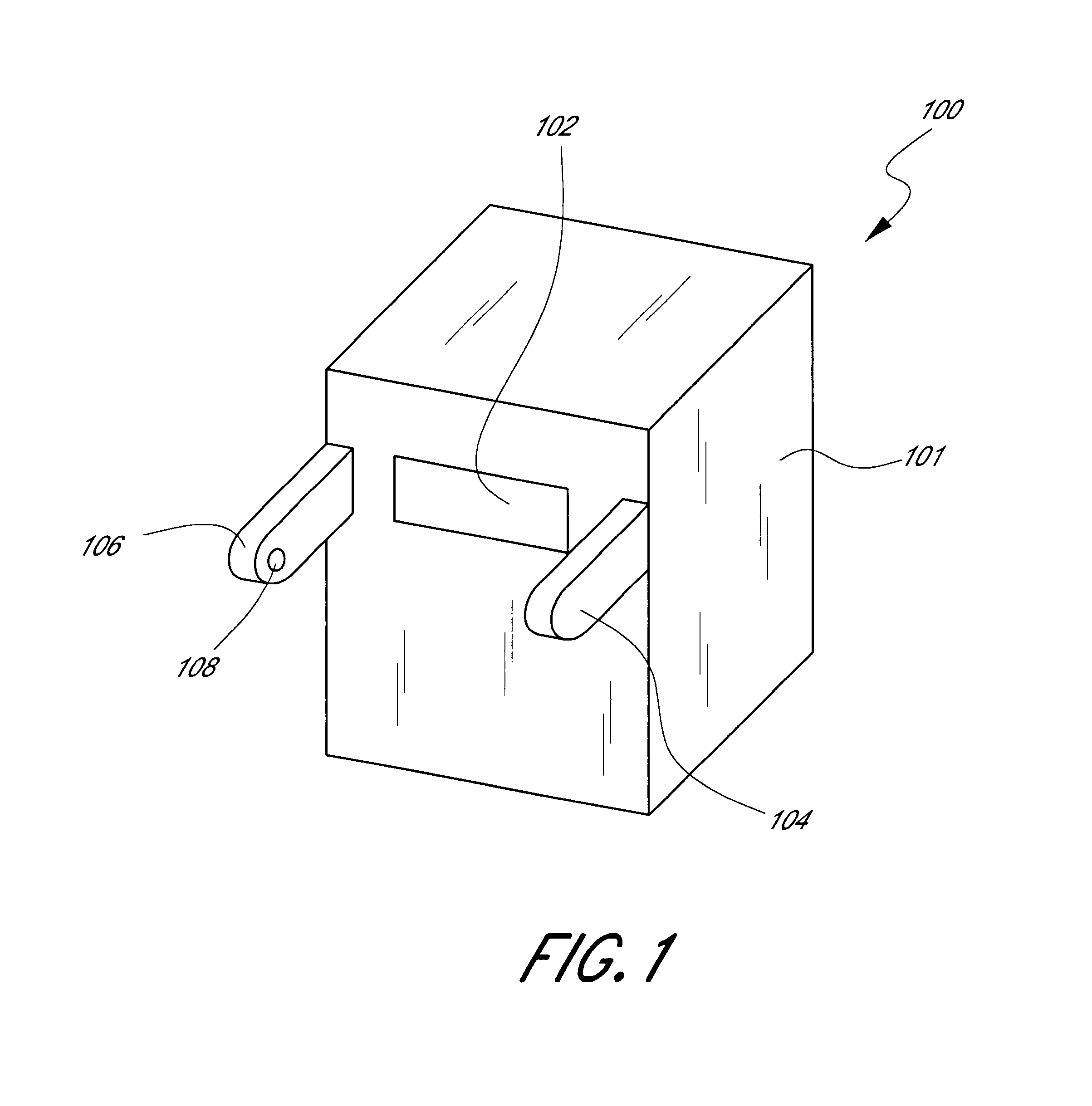
Referring initially to FIG. 1, the wavefront measurement system of the present invention is shown and generally designated 100. FIG. 1 shows that the wavefront measurement system 100 includes a main housing 101 in which a slot 102 allows for one or two cameras (not shown) to be placed in order to image the front of a patient (not shown), while allowing the patient to look at a virtual or real fixation target. Additionally, there may be a right housing 104 and a left housing 106, each extending from the main housing 101 and each having an opening 108 for a camera (not shown).

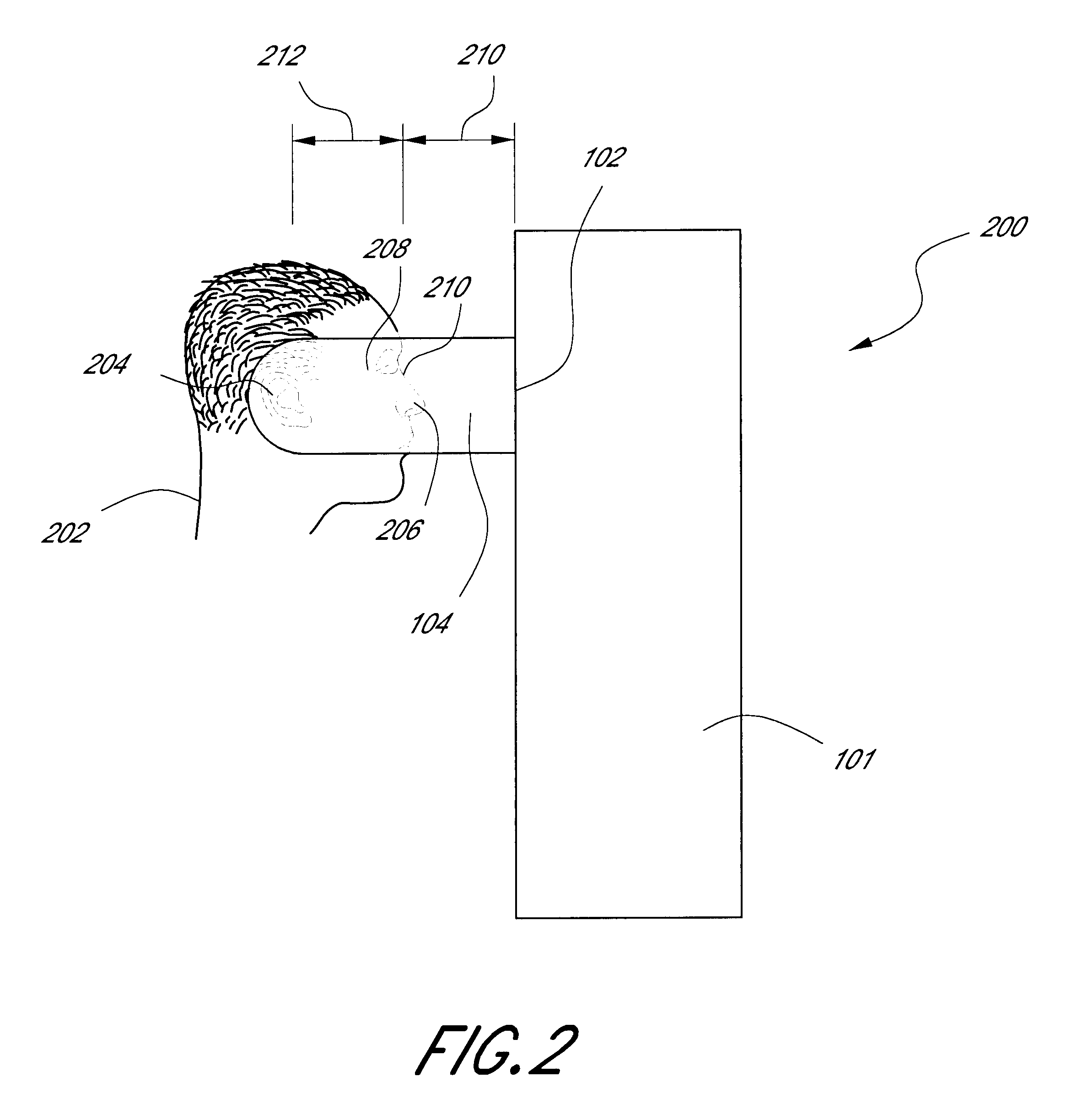
Referring now to FIG. 2, the wavefront measuring system of FIG. 1 is shown from a side view and is generally designated 200. FIG. 2 shows a patient 202 facing the wavefront measuring system main housing 101 and slot 102. A camera (not shown) mounted within right housing 104 photographs the side of patient's 202 head, including the patient's 202 ear 204 and nose 206. The camera or cameras mounted in slot 102 image...


PUM


Abstract

A Custom Eyeglass Manufacturing Method includes a wavefront measuring device with a plurality of cameras directed at a patient's face. The resulting images are processed by a computer to determine the location of pupils, center of pupils, pupil distance, width of face, ear location, distance of corneal apex from the wavefront measuring device, distance from ear to corneal apex, and other desired parameters necessary to quantify a patient's face for custom eyeglass fittings. Moldings may be applied to patient's nose, temples, and ears in order to construct a pair of eyeglasses that fix perfectly on patient's head. Additionally, a test frame may be used in combination with the wavefront measuring device in order to allow computer to find some of the areas automatically. Lastly, registration markers may be applied to either the test frame, the moldings, or both in order to further aide the computer in locating desired parameters.

Description

The present invention relates generally to a custom eyeglass manufacturing method. More specifically, the present invention pertains to developing a manufacturing method that combines a wavefront measuring device with an imaging system that acquires data from a patient's head. The present invention is particularly, though not exclusively, useful for spectacles that correct for aberrations other than sphere, cylindrical, and axis.Current eyeglass manufacturing technology does not provide lenses that precisely correct a patient's wavefront aberrations. However, new manufacturing techniques that make use of epoxies, cured to different indexes of refraction matching the wavefront aberrations of a patient, present new manufacturing challenges. Specifically, alignment of the spectacle with the patient's optical axis is of the utmost importance when making spectacle lenses that correct for aberrations other than spherical, cylindrical, and axis. In order to ensure such precise alignment, t...

Claims


Application Information

Patent Timeline
Patent Type & Authority Patents(United States)
IPC IPC(8): G02C13/00A61B3/10G06F17/50G06T1/00
CPCG02C13/003G02C13/005G02C5/126
Inventor DREHER, ANDREAS W.
Owner ESSILOR INT CIE GEN DOPTIQUE
Why Eureka
Try Eureka