

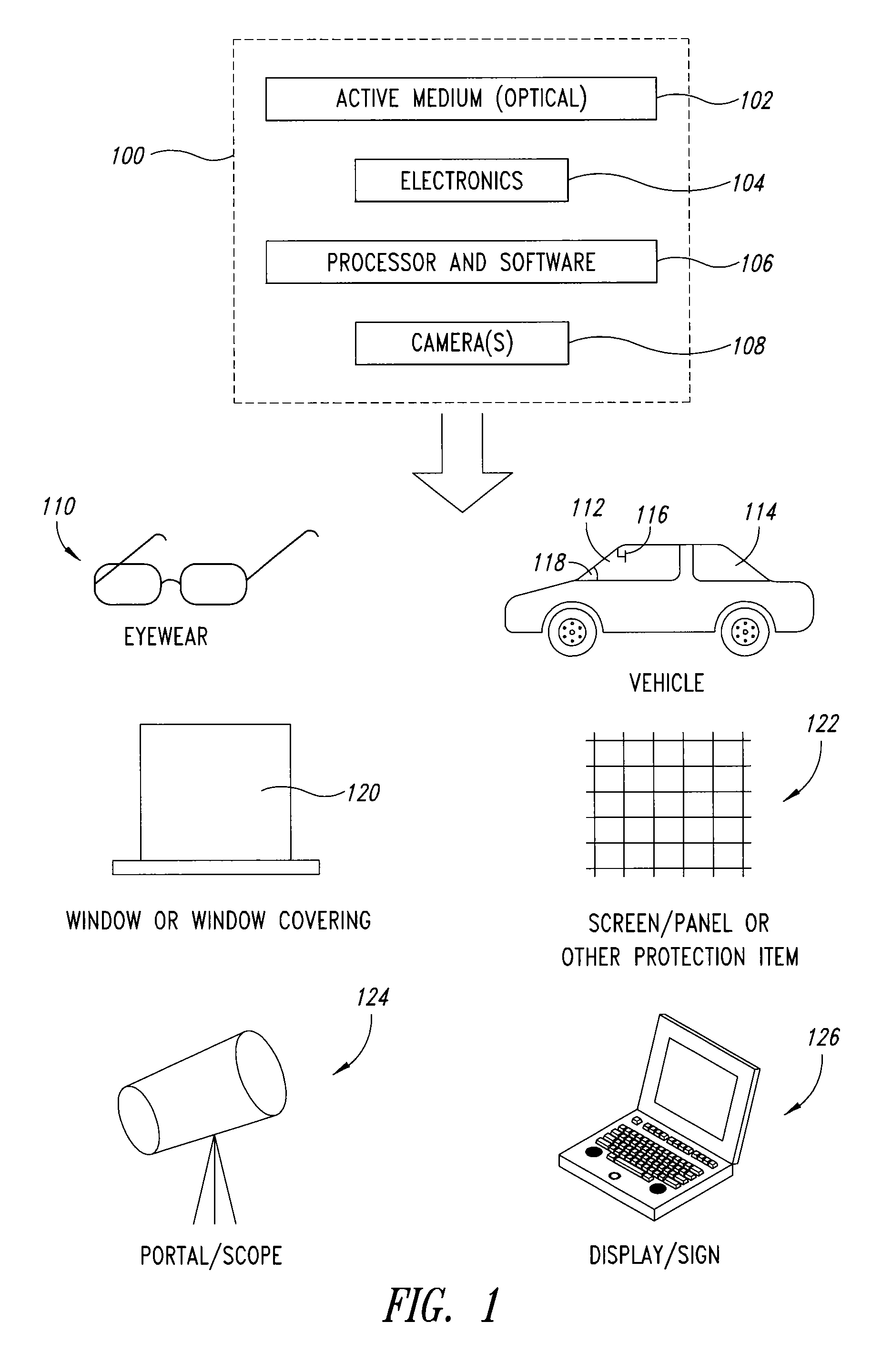
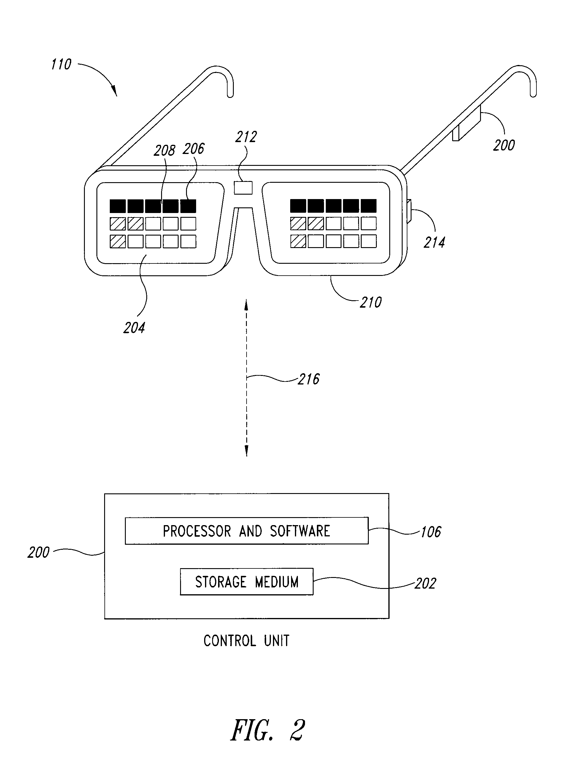
Electrically controlled optical shield for eye protection against bright light
a bright light, electrically controlled technology, applied in the direction of distance measurement, pedestrian/occupant safety arrangement, instruments, etc., can solve the problems of undetectable reduction of the visibility of other portions of the reflected image, deficient devices and techniques in several ways, etc., to achieve the effect of reducing the maximum light level inciden
- Summary
- Abstract
- Description
- Claims
- Application Information
AI Technical Summary
Benefits of technology
Problems solved by technology
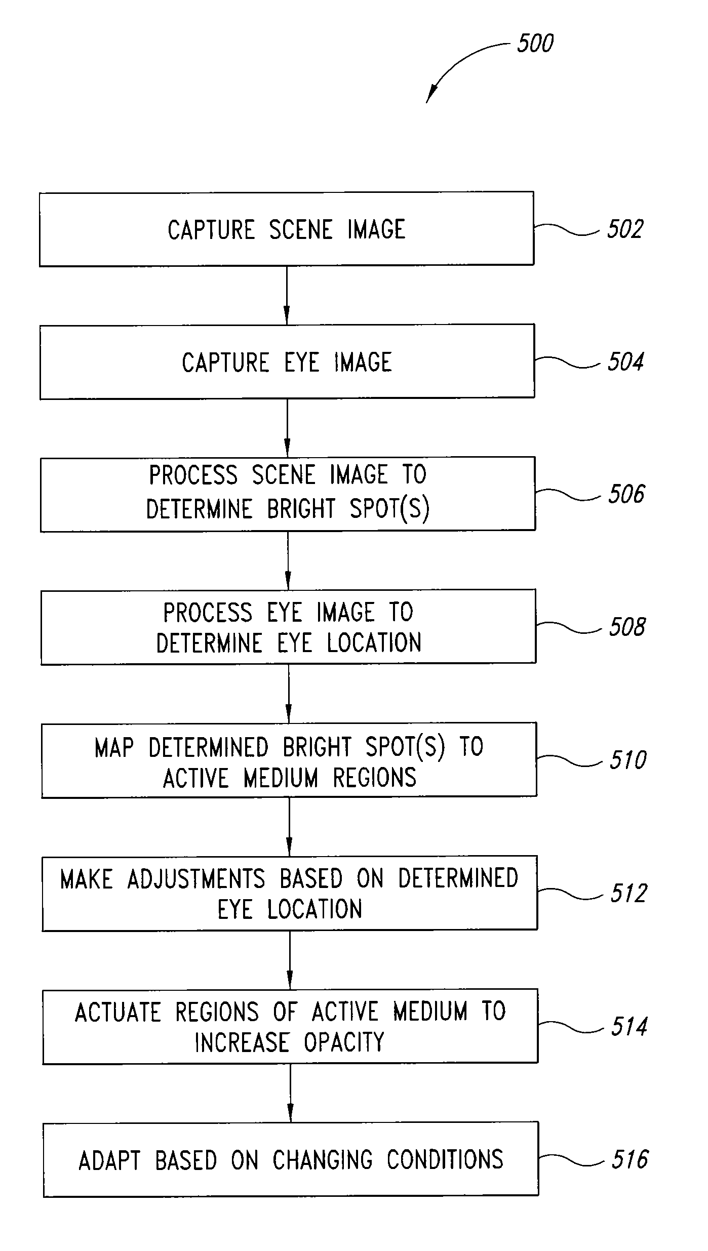
Method used
Image

Examples
Embodiment Construction
In the following description, numerous specific details are given to provide a thorough understanding of embodiments. One skilled in the relevant art will recognize, however, that the invention can be practiced without one or more of the specific details, or with other methods, components, materials, etc. In other instances, well-known structures, materials, or operations are not shown or described in detail to avoid obscuring aspects of the invention.
Reference throughout this specification to “one embodiment” or “an embodiment” means that a particular feature, structure, or characteristic described in connection with the embodiment is included in at least one embodiment. Thus, the appearances of the phrases “in one embodiment” or “in an embodiment” in various places throughout this specification are not necessarily all referring to the same embodiment. Furthermore, the particular features, structures, or characteristics may be combined in any suitable manner in one or more embodime...
PUM
 Abstract
Description
Claims
Application Information