
Stereoscopic 3-d viewing system with portable electro-optical viewing glasses and shutter-state control signal transmitter having multiple modes of operation for stereoscopic viewing of 3-d images displayed in different stereoscopic image formats

a technology of shutter-state control and stereoscopic image, which is applied in the field of stereoscopic 3d viewing system with portable electrooptical viewing glasses and shutter-state control signal transmitters, can solve the problems that composite ntsc or pal video signals generated from vcr players cannot be used to produce video graphics on crt-based computer video monitors without special signal conversion equipment, and cannot be used to produce video graphics on crt-based computer video monitors. the effect of increasing th

Inactive Publication Date: 2002-09-24
REVEO
View PDF11 Cites 186 Cited by
  • Summary
  • Abstract
  • Description
  • Claims
  • Application Information

AI Technical Summary

Benefits of technology

Another object of the present invention is to provide such a system, in which signal decoding and processing is minimized within the stereoscopic 3-D shutter-type viewing glasses in order to reduce the cost of manufacture thereof, while providing extended battery life.
Another object of the present invention is to provide shutter glasses which do not require any background excitation voltage to keep the shutters in the optically transmissive state.

Problems solved by technology

From a practical point of view, VGA or SVGA video signals generated from a graphics accelerator / video board within a computer graphics workstation cannot be used to produce video graphics on a CRT-based television set without the use of special signal conversion equipment.
Similarly, composite NTSC or PAL video signals generated from VCR player cannot be used to produce video graphics on a CRT-based computer video monitor without the use of such special signal conversion equipment.
However, there does not exist a pair of LCD shutter glasses that can be used with either type of CRT display device.
Prior art LC shutter glasses suffer from a number of shortcomings and drawbacks.
Moreover, such circuitry utilizes battery power, and thus shortens the effective life of the batteries aboard the electro-optical shutter glasses.

Method used


Image

  • Stereoscopic 3-d viewing system with portable electro-optical viewing glasses and shutter-state control signal transmitter having multiple modes of operation for stereoscopic viewing of 3-d images displayed in different stereoscopic image formats
  • Stereoscopic 3-d viewing system with portable electro-optical viewing glasses and shutter-state control signal transmitter having multiple modes of operation for stereoscopic viewing of 3-d images displayed in different stereoscopic image formats
  • Stereoscopic 3-d viewing system with portable electro-optical viewing glasses and shutter-state control signal transmitter having multiple modes of operation for stereoscopic viewing of 3-d images displayed in different stereoscopic image formats

Examples


Embodiment Construction

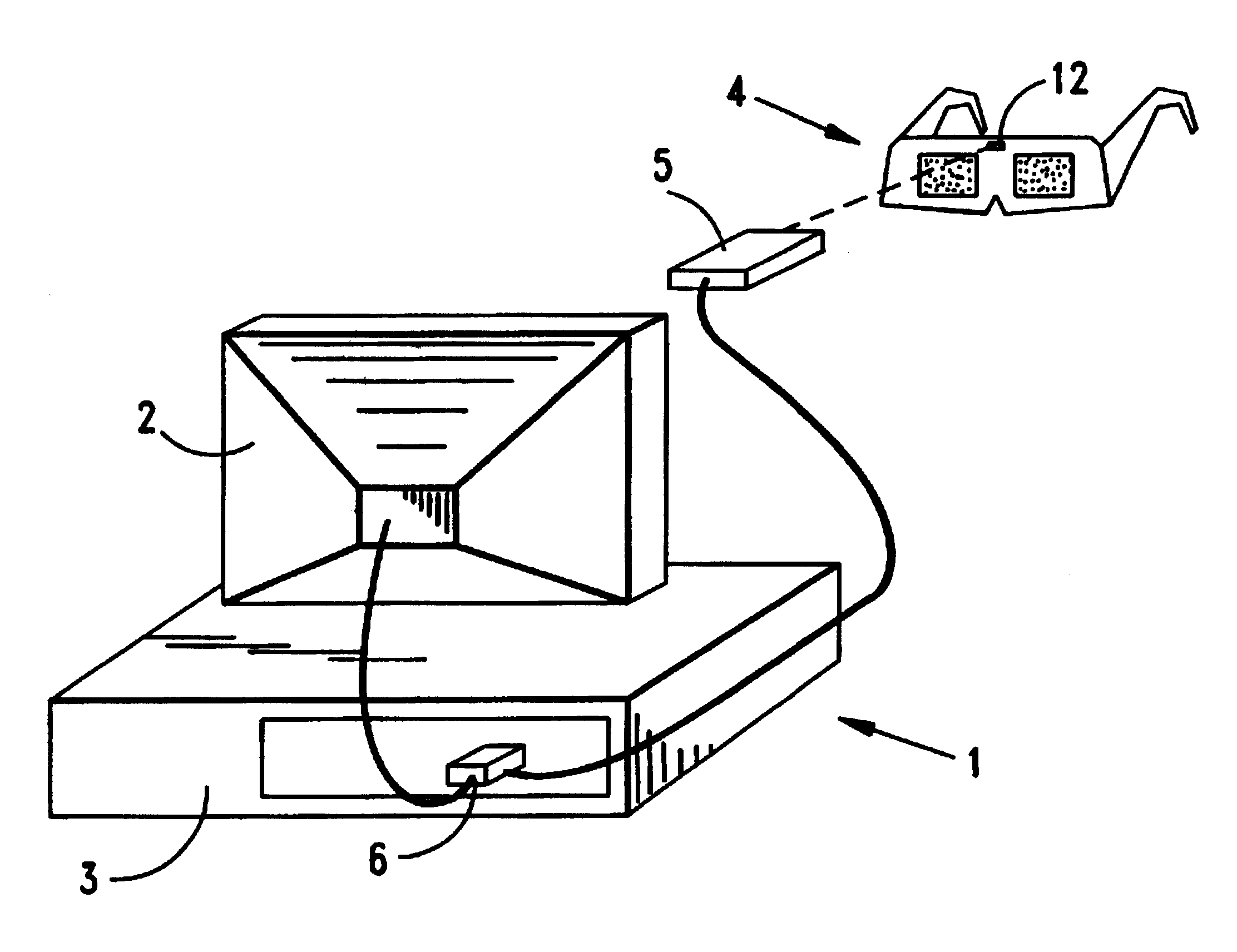
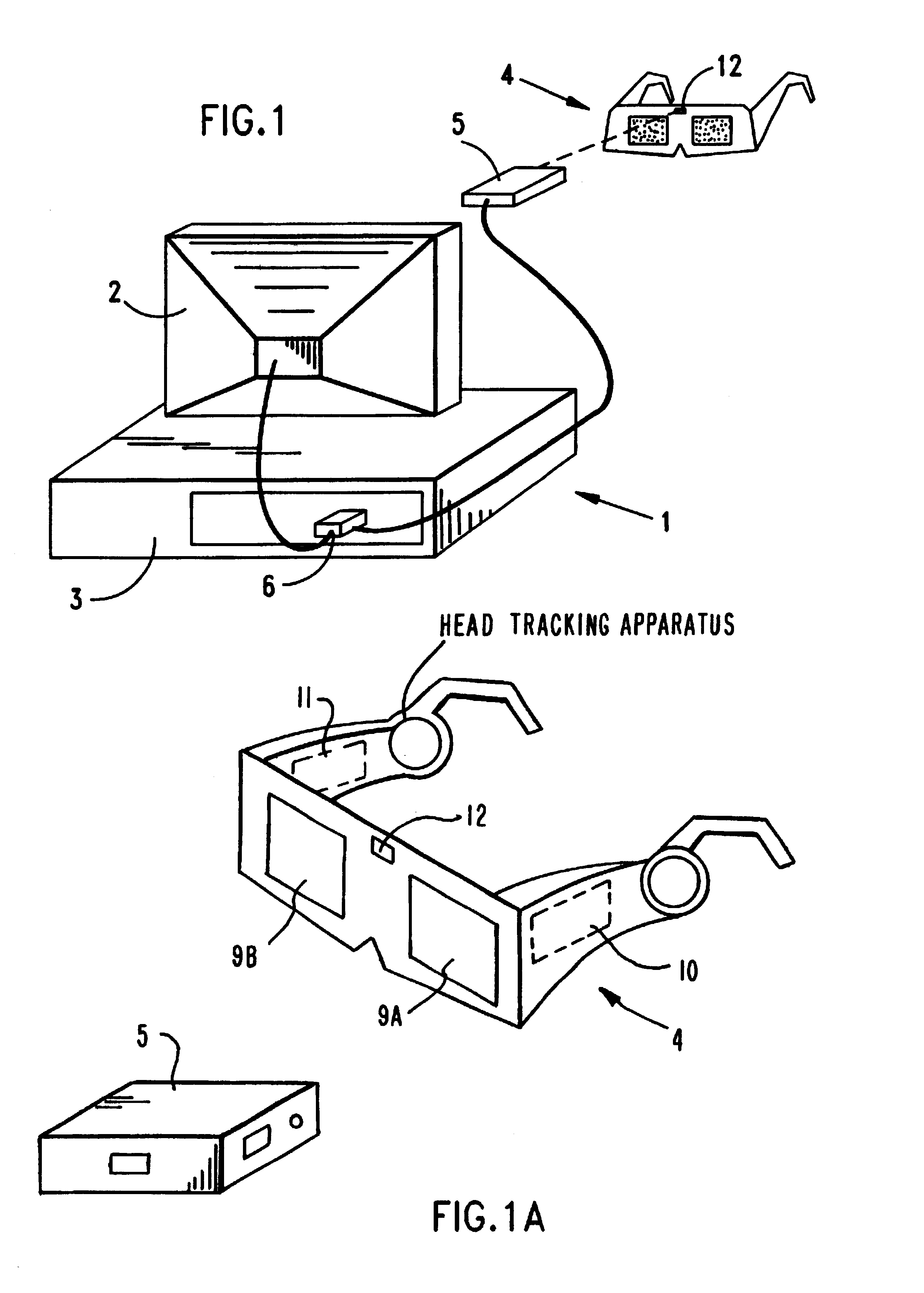
As shown in FIG. 1, the stereoscopic 3-D image viewing system of the present invention 1 comprises a number system components, namely: a CRT-based display device 2; a video signal source 3 for producing video signals representative of either 2-D images, or stereoscopic image pairs for 3-D stereoscopic viewing using the time-multiplexed (i.e. field-sequential) display format; wireless stereoscopic 3-D eyewear (e.g. viewing glasses) 4 having left and right electro-optical viewing shutters for the left and right eyes of its user, respectively; and a remote transmitting device 5 for (i) generating shutter-state control signals (through real-time vertical and horizontal synchronization signal analysis), (ii) encoding these shutter-state control signals, and (iii) transmitting the same to one or more stereoscopic 3-D viewing glasses wirelessly lined to the transmitter, for reception, decoding and use in switching the optical states of the viewing shutters (e.g. from optically opaque to op...


PUM

PropertyMeasurementUnit
thicknessaaaaaaaaaa
optical stateaaaaaaaaaa
3-D depth sensationaaaaaaaaaa

Abstract

The present invention relates to a system and method of viewing pairs of perspective images of 3-D objects (i.e. stereoscopic image pairs) displayed from a CRT display surface in a time-multiplexed or field-sequential manner, and more particularly to a universal method of generating control signals for synchronously changing the optical state of liquid crystal (LC) shutter panels through which the time-multiplexed perspective. images can be sequentially viewed in a substantially flicker-free manner by the left and right eyes of a human viewer, independent of whether the images are displayed on NTSC, PAL, VGA or SVGA styled CRT display devices.

Description

1. Field of the InventionThe present invention relates to a system and method of viewing pairs of perspective images of 3-D objects (i.e. stereoscopic image pairs) displayed from a CRT display surface in a time-multiplexed or field-sequential manner, and more particularly to a universal method of generating control signals for synchronously changing the optical state of liquid crystal (LC) shutter panels through which the time-multiplexed perspective images can be sequentially viewed in a substantially flicker-free manner by the left and right eyes of a human viewer, independent of whether the images are displayed on NTSC, PAL, VGA or SVGA styled CRT display devices.2. Brief Description of the Prior ArtDuring the course of human history, man has developed numerous ways of displaying two-dimensional (2-D) images of real and synthetic images alike. In many ways, the evolution of image display technology can be linked to particular stages of development in human civilization.In the con...

Claims


Application Information

Patent Timeline
Patent Type & Authority Patents(United States)
IPC IPC(8): G02B27/26G02F1/1335G02B27/22G02B27/00G02F1/13G06F1/16G03B21/132G03B21/30G06F3/033G06F3/00G06K15/00G06K15/22H04N13/00H04N5/74G02F1/1334G02B30/25G02F1/13357G06F3/01G06F3/041G06F3/048H04N13/363
CPCG03B21/30G06F3/041G06F3/0412G06F3/0414G06K15/00G06K15/22H04N5/7441H04N9/3141H04N13/0037H04N13/0048H04N13/0051H04N13/0055H04N13/0059H04N13/0239H04N13/0242H04N13/0246H04N13/0275H04N13/0278H04N13/0296H04N13/0422H04N13/0434H04N13/0438H04N13/0454H04N13/0459H04N13/0475H04N13/0477H04N13/0481H04N13/0497G02B27/0093G02B27/2264G02B27/26G03B21/132G06F3/011H04N19/597G06K2215/0082H04N5/7491H04N13/0025H04N13/004H04N13/0203H04N13/0217H04N13/0257H04N13/0285H04N13/0289H04N13/0425H04N13/0431H04N13/044H04N13/0456H04N13/047H04N13/0484H04N2213/008G02F1/1334G02F2001/133538H04N13/337H04N13/341H04N13/289H04N13/167H04N13/243H04N13/344H04N13/194H04N13/279H04N13/275H04N13/189H04N13/376H04N13/156H04N13/324H04N13/246H04N13/368H04N13/38H04N13/257H04N13/161H04N13/296H04N13/218H04N13/204H04N13/334H04N13/363H04N13/286H04N13/15H04N13/373H04N13/359H04N13/361H04N13/327H04N13/383H04N13/398H04N13/133G02B30/24G02B30/25G02F1/133538
Inventor LAZZARO, GERARD M.SWIFT, DAVID C.HAMLIN, GREGORY J.FARIS, SADEG M.
Owner REVEO
Learn More