Upright vacuum cleaner

Inactive Publication Date: 2012-04-05
SAMSUNG ELECTRONICS CO LTD
View PDF1 Cites 11 Cited by
  • Summary
  • Abstract
  • Description
  • Claims
  • Application Information

AI Technical Summary

Benefits of technology

[0008]Therefore, it is an aspect of the present disclosure to provide an upright vacuum cleaner which i

Problems solved by technology

However, the above conventional vacuum cleaners have a complicated structure and thus increase manufacturing costs and repair and maintenance costs.
Further, in the conventional vacuum cleaners, an operation of swiveling a cleaner body a

Method used


Image

  • Upright vacuum cleaner
  • Upright vacuum cleaner
  • Upright vacuum cleaner

Examples


Embodiment Construction

[0028]Reference will now be made in detail to the embodiments of the present disclosure, examples of which are illustrated in the accompanying drawings, wherein like reference numerals refer to like elements throughout.

[0029]Hereinafter, an upright vacuum cleaner 1 in accordance with an embodiment of the present disclosure will be described in detail with reference to the accompanying drawings.

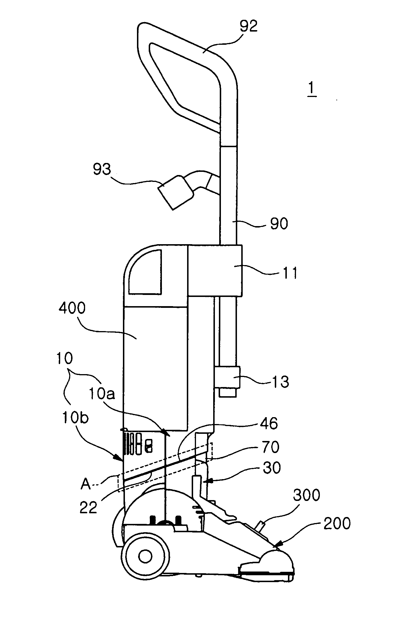
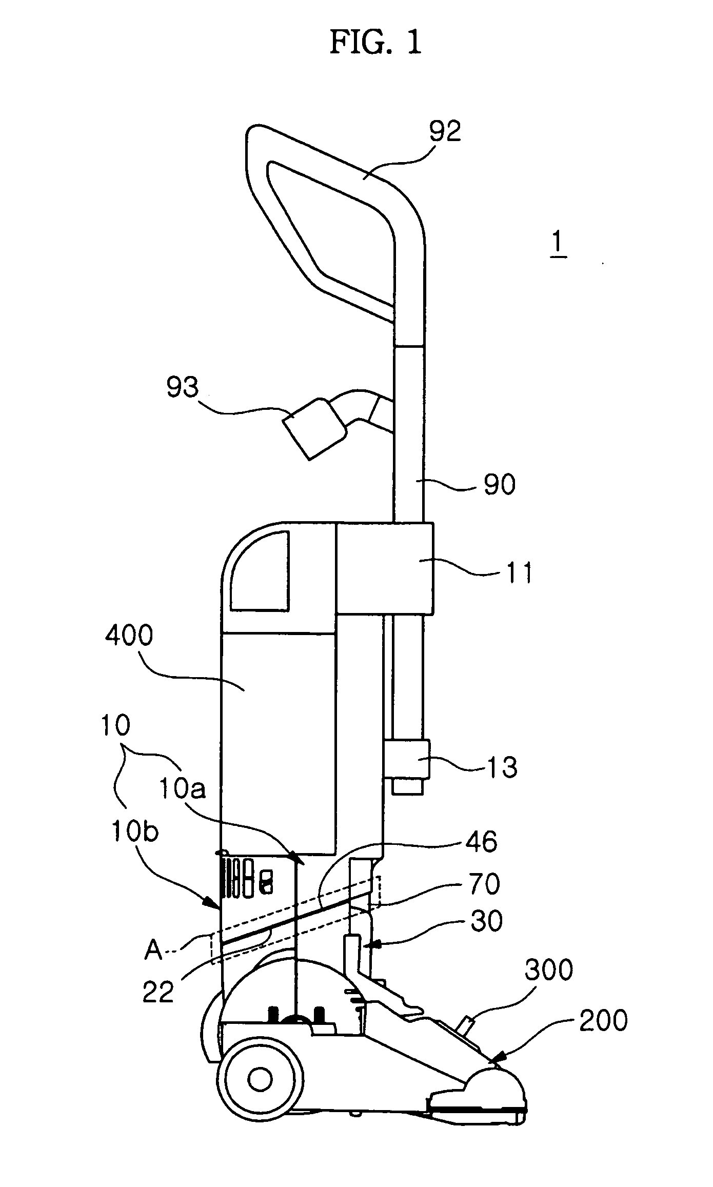
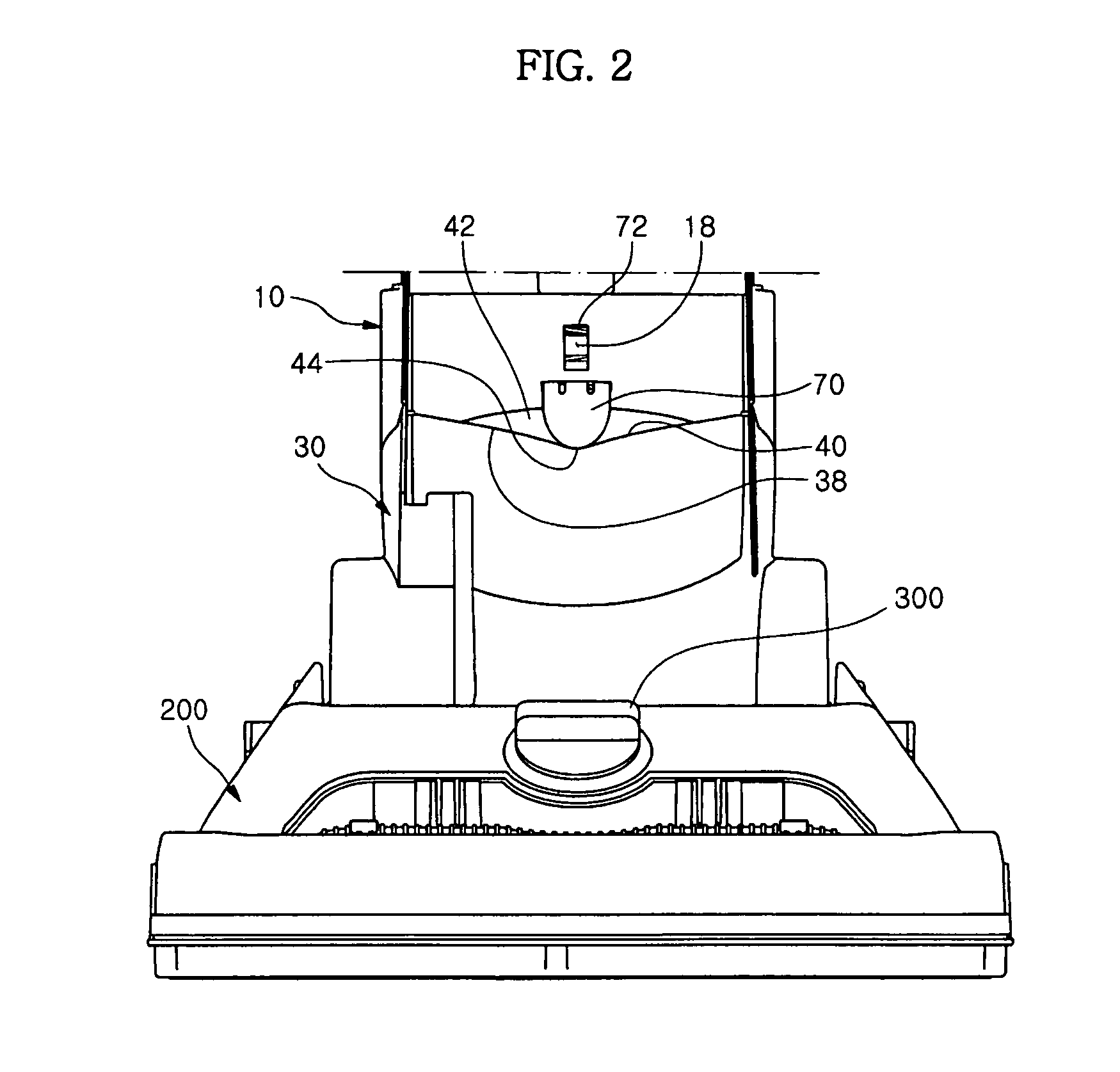
[0030]With reference to FIGS. 1 to 4, the upright vacuum cleaner 1 in accordance with the embodiment of the present disclosure includes a nozzle assembly 200, an upper body 10, a lower body 30, a bearing member 60, a steering unit 70 and a dust collecting device 400.

[0031]With reference to FIGS. 1 and 2, the nozzle assembly 200 is connected with the lower body 30 and is provided with a height adjustment lever 300. Further, the nozzle assembly 200 is provided with an air suction hole (not shown) and a rotating brush (not shown). The lower body 30 may be tilted with respect to the nozzle assembl...


PUM


Abstract

An upright vacuum cleaner includes a nozzle assembly, a lower body pivotally connected to the nozzle assembly and provided with an inclination unit on the outer circumferential surface of the lower body, an upper body rotatably connected to the lower body, a bearing member installed between the lower body and the upper body, a steering unit contacting the inclination unit and elastically installed on the upper body, wherein, when the upper body is swiveled with respect to the lower body, the steering unit is moved upwards and downwards by the inclination unit and then applies pressure to the upper body so as to return the upper body to its original position.

Description

CROSS-REFERENCE TO RELATED APPLICATIONS[0001]This application claims the priority benefit of Korean Patent Application No. 2010-0095035, filed on Sep. 30, 2010 in the Korean Intellectual Property Office, the disclosure of which is incorporated herein by reference.BACKGROUND[0002]1. Field[0003]Embodiments of the present disclosure relate to an upright vacuum cleaner which is easy to change direction and to return a cleaner upper body to its original position.[0004]2. Description of the Related Art[0005]When a surface is cleaned using a vacuum cleaner, the vacuum cleaner needs to be easy to change direction and to return a body which is twisted due to such direction change to its original position for ease of use. Particularly, if a relatively heavy upright vacuum cleaner is used, in order to conveniently and easily operate the vacuum cleaner, the direction of a cleaner nozzle assembly contacting a floor, needs to be easy to change by turning a cleaner handle like a vehicle handle and...

Claims


Application Information

Patent Timeline
IPC IPC(8): A47L9/02A47L5/00
CPCA47L9/009A47L5/28
Inventor SEO, JI WON
Owner SAMSUNG ELECTRONICS CO LTD
Why Eureka
Try Eureka