Flying disk

A flying saucer and flywheel technology, applied in the field of aircraft, can solve the problems of high maintenance and use cost, complicated air flight control, high energy consumption, etc., and achieve the effects of fast or slow speed, improved flying saucer power, and increased propulsion speed.

Inactive Publication Date: 2008-07-16
陈久斌
View PDF0 Cites 11 Cited by
  • Summary
  • Abstract
  • Description
  • Claims
  • Application Information

AI Technical Summary

Problems solved by technology

[0002] Existing aircraft mainly include airplanes, helicopters, spacecraft, and rockets. Airplanes have many defects, such as: take-off and landing are restricted by various conditions, and most of them cannot take off and land vertically; the flight speed is not high enough; energy consumption is high; Complicated control; clumsy air flight movements; unable to fly due to special weather, etc.
Helicopters have defects such as low flight speed, high energy consumption, and inability to fly due to special weather; spaceships have defects such as low flight speed, inability to realize galaxy navigation, difficulty in taking off and landing, and difficulty in entering the atmosphere
These aircraft generally have problems such as poor safety and high maintenance and use costs
None of the existing aircraft can dive, let alone a submarine
Most aircraft cannot use nuclear power

Method used


Image

  • Flying disk
  • Flying disk
  • Flying disk

Examples


Embodiment Construction

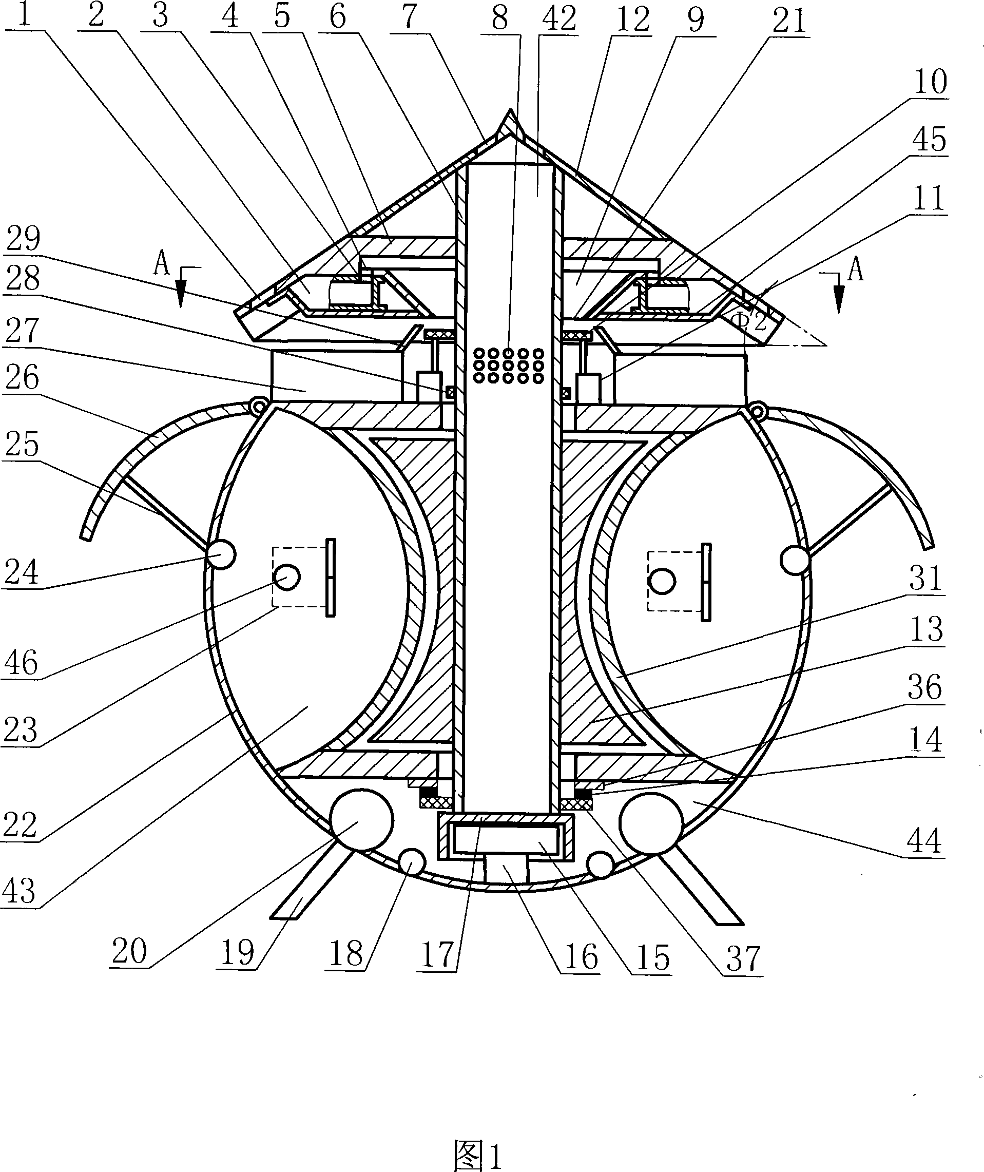
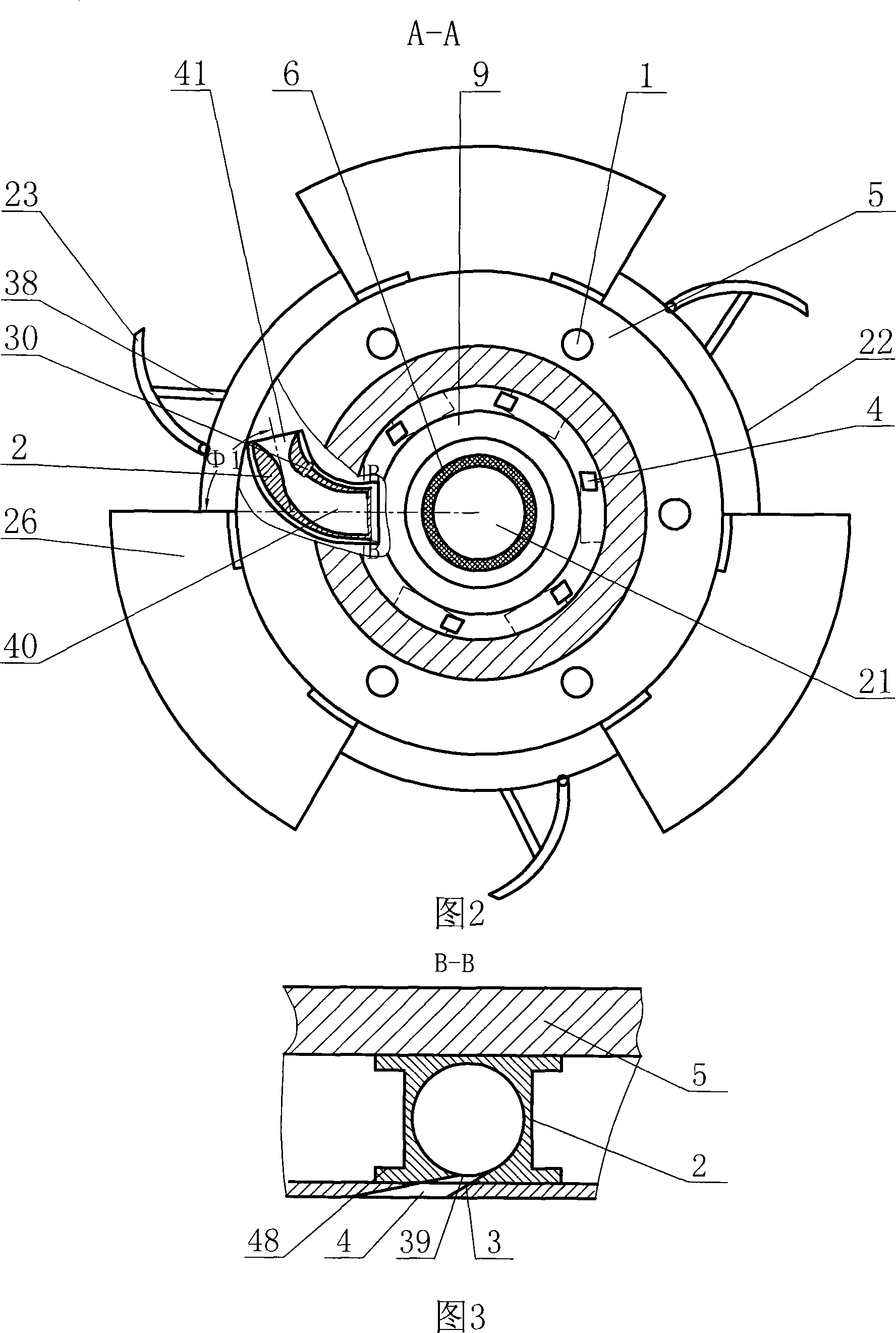
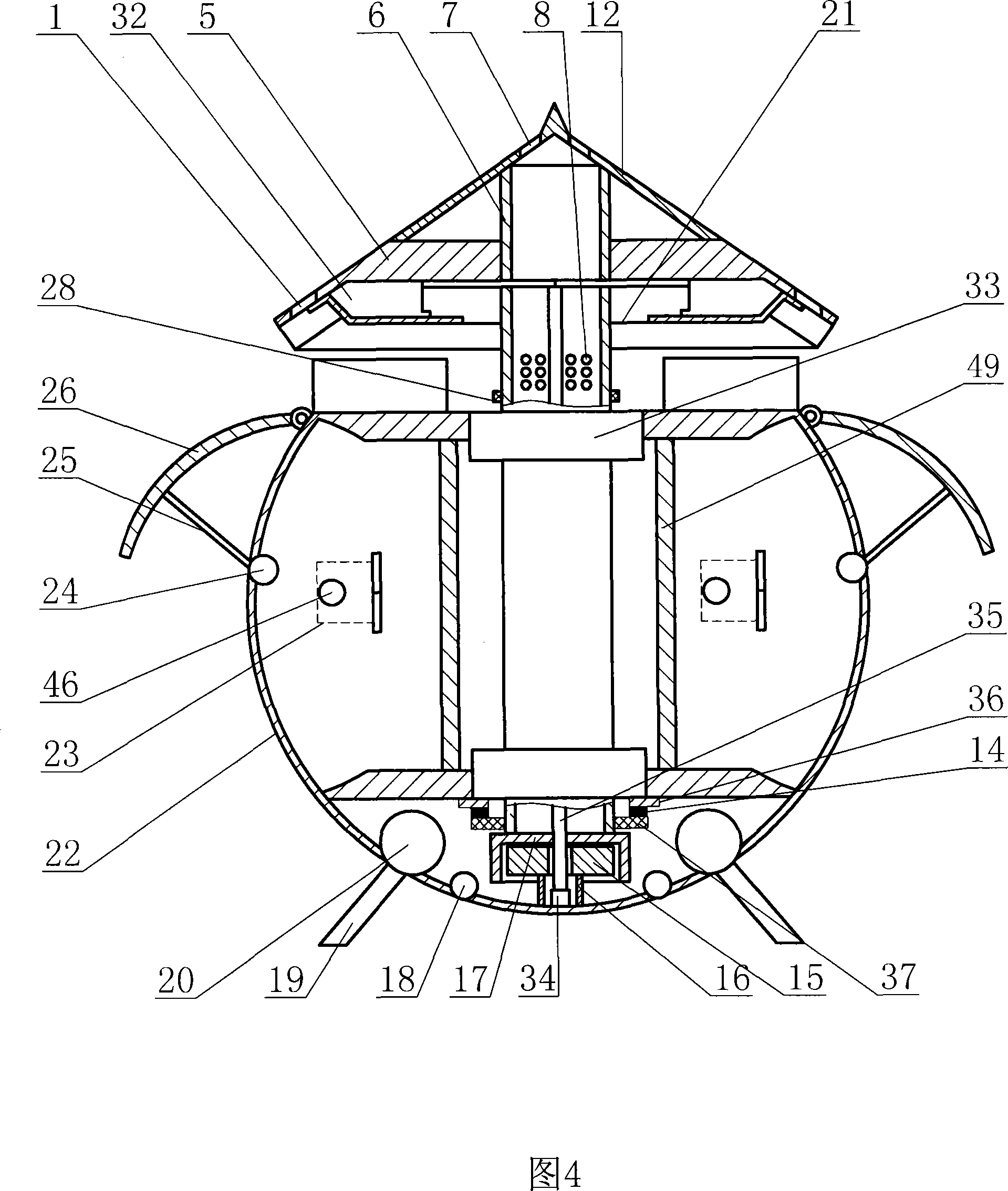
[0008] The main structure of the present invention is: flying saucer, comprising cabin body 22, control system, electrical system, cabin facilities, fuel system, starting system and ignition system, cabin body motion direction regulating device and cabin body rotation stability adjustment are installed on the cabin body 22 Device, fuel tank 27 is installed on the cabin body 22, and fuel pipe 29 is set on the fuel tank 27, and flywheel jet engine is installed on the cabin body 22, and flywheel jet engine comprises flywheel shaft 6, flywheel 5 and jet device, flywheel shaft 6 and cabin body 22 Connection, the flywheel 5 is installed on the flywheel shaft 6, and multiple air injection devices are installed on the periphery of the flywheel 5. The angle between the air injection direction of the air injection device and the radius of the flywheel 5 is Φ1. After research, the optimal value of Φ1 ranges between 55.62°-68.76° , can help to overcome part of the centrifugal force to offs...


PUM


Abstract

The invention discloses a flying saucer, belonging to an aircraft field; the invention comprises a cabin, an operation and control system, an electric system, a plurality of facilities inside cabin, a fuel system, a starting system and an ignition system; a device for regulating motion direction of the cabin and a device for regulating rotary stability of the cabin are arranged on the cabin; a fuel tank is arranged on the cabin and a fuel pipe is arranged on the fuel tank; a flywheel jet engine is arranged on the cabin and the flywheel jet engine includes a flywheel shaft, a flywheel and a jet device; the jet shaft is connected with the cabin; the flywheel is arranged on the flywheel shaft and a pluratliy of jet devices is arranged on the periphery of the flywheel. The flying saucer can realize vertical takeoff and landing; the invention is provided with the device for regulating the motion direction of the cabin and the device for regulating the rotary stability of the cabin; the flying saucer has simple operation, stable flight and convenient direction-changing; in the flight of the flying saucer, a spiral flow which surrounds the cabin, rotates around the cabin and at the same time spirally propels downwards the cabin is generated, thus greatly accelerating propelling speed of the flow downwards the cabin. The invention has the advantages of high flight speed, flexible direction-changing, high safety, and low fuel cost.

Description

technical field [0001] The invention relates to the field of aircraft, in particular to a flying saucer Background technique [0002] Existing aircraft mainly include airplanes, helicopters, spacecraft, and rockets. Airplanes have many defects, such as: take-off and landing are restricted by various conditions, and most of them cannot take off and land vertically; the flight speed is not high enough; energy consumption is high; Complicated controls; clumsy air flight movements; unable to fly due to special weather, etc. Helicopters have defects such as low flight speed, high energy consumption, and inability to fly due to special weather; spacecraft have defects such as low flight speed, inability to realize galaxy navigation, difficulty in taking off and landing, and difficulty in entering the atmosphere. These aircraft generally have problems such as poor safety and high maintenance and use costs. Existing aircraft all can not dive, and submarine more can not fly. Most ...

Claims


Application Information

Patent Timeline
Patent Type & Authority Applications(China)
IPC IPC(8): B64C29/04
CPCG21B3/00G21D5/00Y02E30/00Y02E30/10
Inventor 陈久斌
Owner 陈久斌
Why Eureka
Try Eureka