
Frame face display and shipping container

a display box and frame face technology, applied in the field of shipping containers, can solve the problems of time or labor or expense for inserting the u-shaped paperboard, requiring excessive force or tools to open, and the use of stronger perforations requiring excessive force or tools

Active Publication Date: 2012-04-05
INT PAPER CO
View PDF11 Cites 11 Cited by
  • Summary
  • Abstract
  • Description
  • Claims
  • Application Information

AI Technical Summary

Benefits of technology

[0009]The advantages of the present invention, among others, are that the frame face display and shipping container resolves all the aforementioned problem herein above, while successfully addressing each of the material-handling requirements. It is a one-piece design in a heavy-weight cardboard grade, that is shipped either open-front or with an optional removable top plug panel. This combination of attributes delivers: 1) Good top-to-bottom compression in shipping position 2) An open shop-able (e.g., excellent display and access to product) front that eliminates most of the “free panels” that could come unfolded and look unsightly 3) A “Frame-Face” that augments product presentation, faster and easier setup and loading in customer's production. At the same time, the present invention eliminates 1) the easy damage that happens during removal of the front tear-out panel and accompanying fraying 2) the time, labor, and expense of inserting a custom U-shaped cardboard or paperboard.
[0012]Accordingly, one aspect of the present invention is directed to an open-top container for shipping and displaying products which comprises a plurality of side walls. Bottom wall flaps are foldably joined to bottom edges of the side walls and are folded inwardly therefrom into overlapping relationship with one another to form a bottom wall closure. A respective plurality of triangularly-shaped beams foldably joined to upper edges of the respective plurality of side walls. Each of the plurality of the triangularly-shaped beams is defined by a shoulder panel and a flange panel foldably joined to one another. A bumper sticker panel is foldably joined to upper edge of one of the plurality of side walls forming a partial top closure when the open-top container is in the shipping position and partially prevents products from falling out when the open-top container is in the displaying position.
[0015]Another aspect of the present invention is directed to a shipping and displaying container formed from a one-piece unitary blank of material. The shipping and displaying container comprises a bottom wall, first and second side walls, first and second end walls which all foldably joint with one another. First and second triangularly-shaped beams are foldably joined to upper edges of the respective first and second end walls. Each of the first and second triangularly-shaped beams is defined by a shoulder panel and a flange panel foldably joined to one another. A third triangularly-shaped beam having a pair of shoe-shaped latches foldably joined to upper edge of the second side wall. The pair of shoe-shaped latches foldably joined at lateral opposed ends of the third triangularly-shaped beam to lock and hold the first, second, and the third triangularly-shaped beams into their respective folding position. A bumper sticker panel is foldably joined to upper edge of the first side wall forming a partial top closure when the container is in the shipping position and partially prevents products from falling out when the container is in the displaying position.

Problems solved by technology

The problems with this design were that the outer tears easily during the removal of the front tear-out panel that left jagged edges and often partially unfolded, and the time or labor or expense to insert the U-shaped paperboard.
There have been attempts in the past to manufacture a one-piece displayable container using perforated tear out panels, but these approaches have encountered several problems.
For example, the perforations in previous attempts at such a design are; generally unprotected and located in areas that are highly susceptible to damage during shipping.
This susceptibility to damage has led to premature failure of the perforations or has resulted in the use of stronger perforations requiring excessive force or tools to open.
Further, a perforated window, in itself, does not provide protection to any outside surfaces of a container, resulting in the potential for unattractive packages at retail sites due to gouges or scuffing from the distribution environment.

Method used


Image

  • Frame face display and shipping container
  • Frame face display and shipping container
  • Frame face display and shipping container

Examples


first embodiment

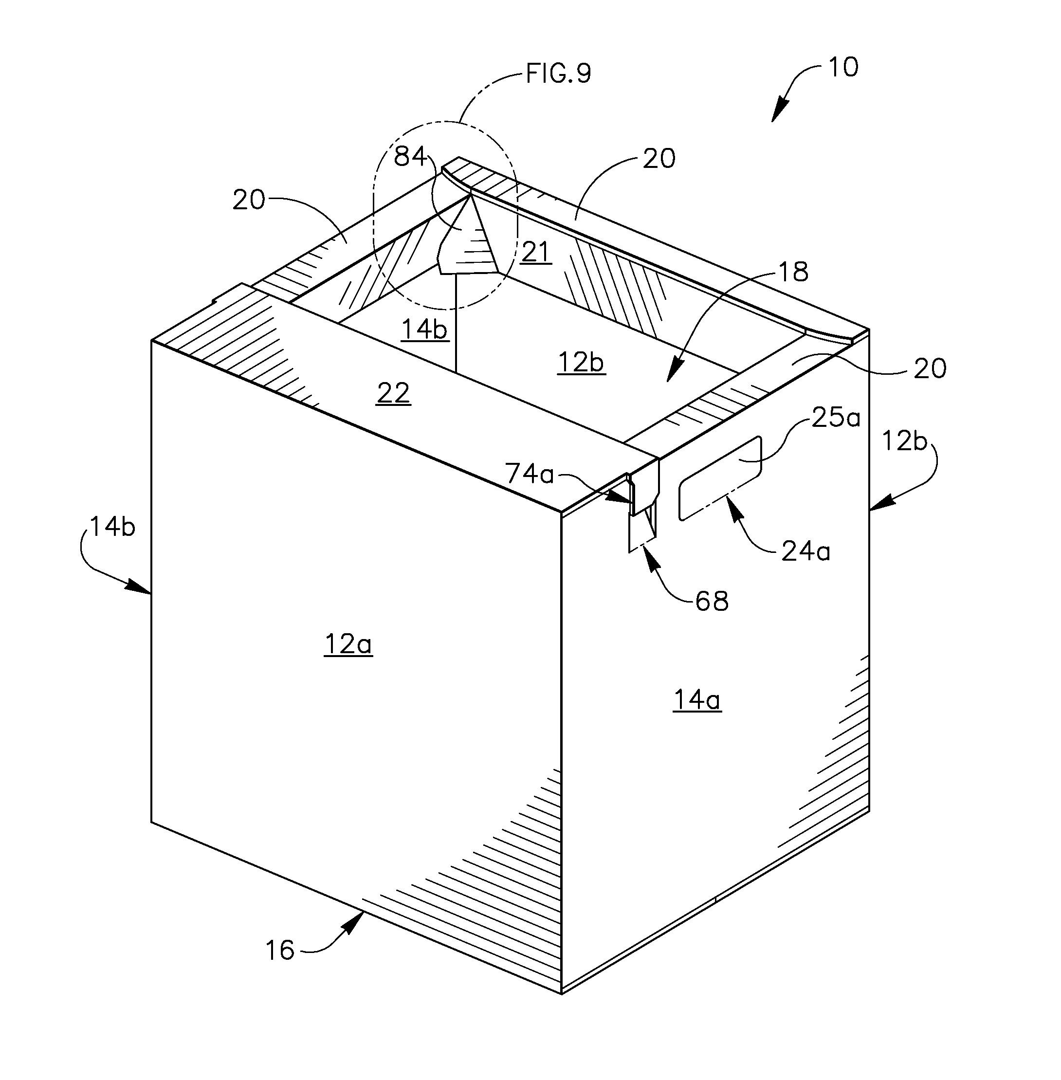
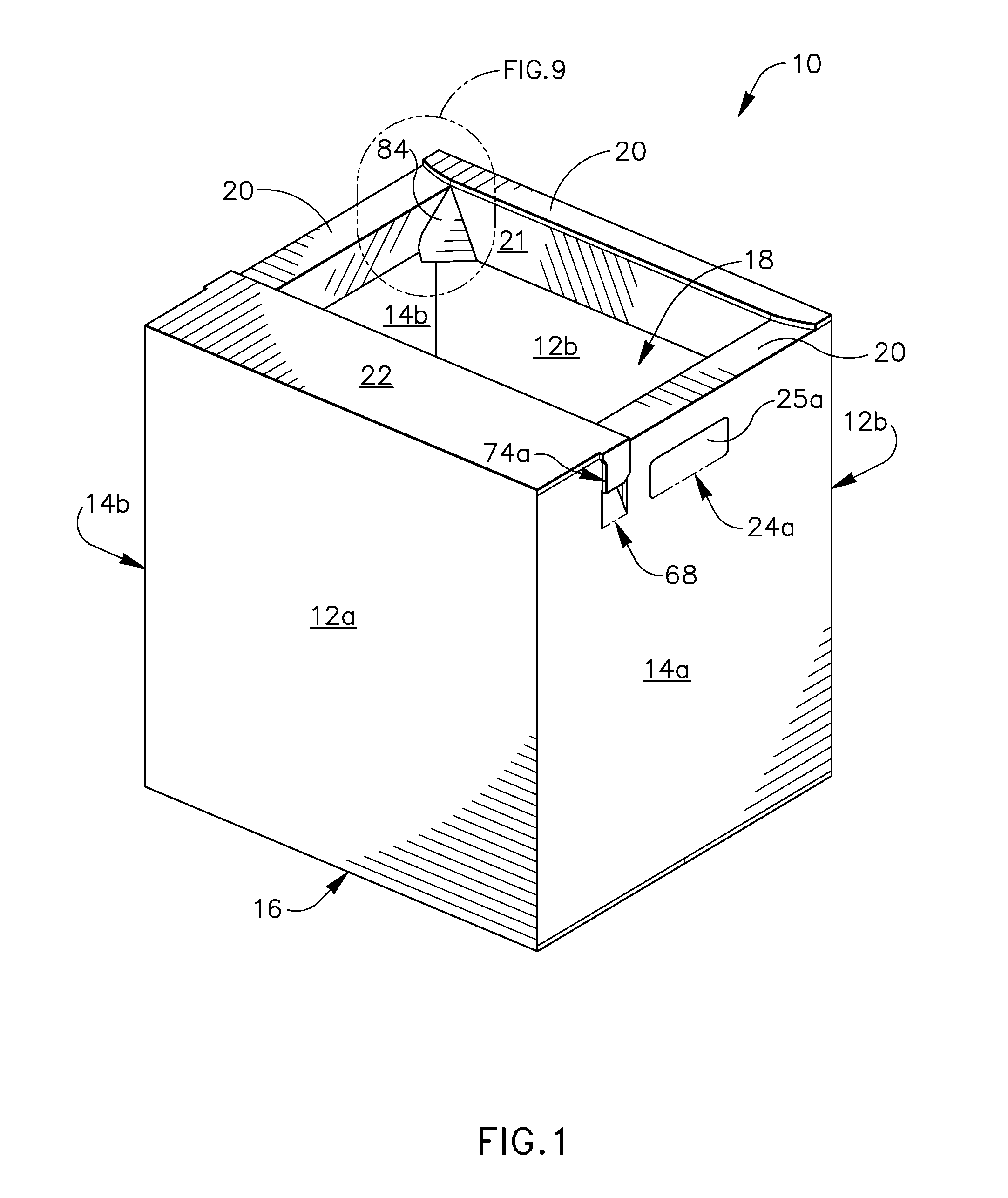
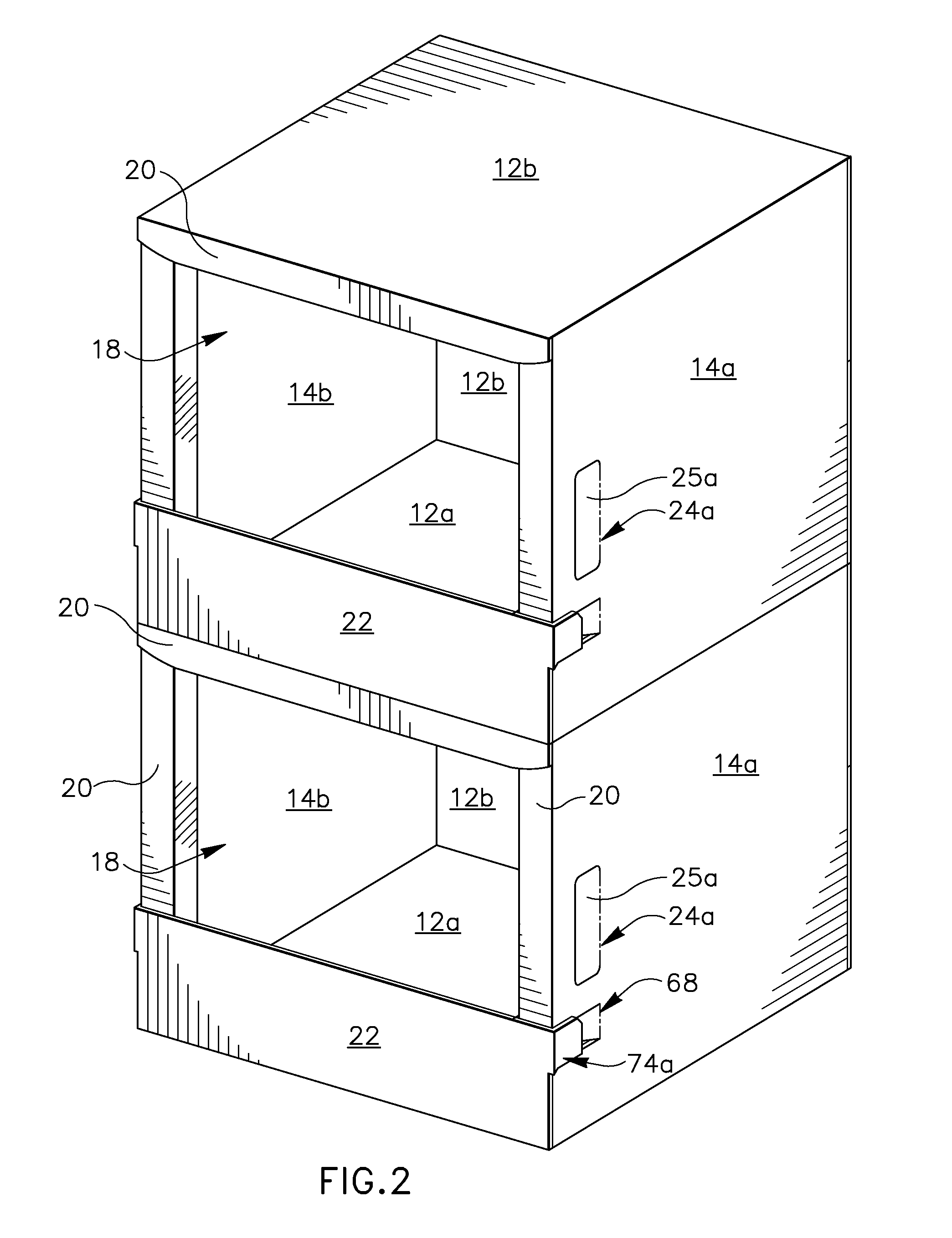
[0030]FIG. 1 is a top perspective view of a frame face or open-top shipping and displaying container 10 according to the present invention. The container 10 includes side walls 12a, 12b, end walls 14a, 14b, and a bottom wall 16 that are all integrally attached to one another. The container 10 has an open top or opening 18. Although the container 10 is characterized as having side walls and end walls, but one of the ordinary skilled in the art would appreciate that the end walls can be defined as side walls as well and the characterization of the side walls and end walls have no effect on the function or utility of the container 10. The open-top container 10 includes shoulders 20 that provide bearing surface for the next container on top of it when the containers 10 are stacked on one another in shipping position. The frame face shipping and displaying container 10 also includes a bumper sticker panel 22 that is used to partially prevent products from falling out when the container 1...

second embodiment

[0033]FIG. 5 is a top perspective view of alternative shipping and displaying container 10 according to the present invention. In this embodiment, the bumper sticker panel 22 is held in position by a means other than the straps off of its sides. The means may include adhesive and tape or an extension of the bumper sticker decal itself.

[0034]FIG. 7A is a plan view of a blank B1 used to form the shipping and displaying container 10 shown in FIG. 1 and FIG. 7B is a top perspective view of the blank B1 in FIG. 7A, showing a first step used to form the shipping and displaying container 10 shown in FIG. 1, wherein one edge of the side walls is attached to the glue panel 72. The blank B1 is substantially flat symmetrical with respect to its longitudinal axis thereof. The blank B1 is preferably an integral piece of a material such as continuous sheet of conventional corrugated cardboard. The blank B1 is cut along its outer margins to form its specific shape. The blank B1 is divided into sid...


PUM


Abstract

The present invention is directed to an open-top container for shipping and displaying products which comprises a plurality of side walls. Bottom wall flaps are foldably joined to bottom edges of the side walls and are folded inwardly therefrom into overlapping relationship with one another to form a bottom wall closure. A respective plurality of triangularly-shaped beams foldably joined to upper edges of the respective plurality of side walls. Each of the plurality of the triangularly-shaped beams is defined by a shoulder panel and a flange panel foldably joined to one another. A bumper sticker panel is foldably joined to upper edge of one of the plurality of side walls forming a partial top closure when the open-top container is in the shipping position and partially prevents products from falling out when the open-top container is in the displaying position.

Description

CROSS REFERENCE TO RELATED APPLICATIONS[0001]This application claims priority to US provisional patent application Ser. No. 61 / 388,933, filed on 1 Oct. 2010, which is hereby incorporated hereinto by reference as if fully restated herein.FIELD OF THE INVENTION[0002]The present invention relates generally to containers for storing, protecting and displaying products and more particularly, to a shipping container that is easily converted into a display container that permits access to and display of the products shipped and contained therein.BACKGROUND OF THE INVENTION[0003]The present invention is directed to a frame face display and shipping container that has dual use of shipping and display characteristic.[0004]In shipping and displaying products, particularly in a retail setting, it is desirable to have a container which is easy to pack, sturdy and fully enclosed for protection of contents during storage and shipping, and also suitable for display at a retail site. For example, it...

Claims


Application Information

Patent Timeline
Patent Type & Authority Applications(United States)
IPC IPC(8): B65D6/18
CPCB65D5/001B65D5/42B65D5/12
Inventor MCCLURE, JACK A.
Owner INT PAPER CO
Learn More