
Printing system, printing method, print server, control method and computer-readable medium

a printing system and control method technology, applied in the direction of digital output to print units, instruments, computing, etc., can solve the problems of loss of thin lines, difficulty in conventional methods designation, and various problems of quality degradation

Inactive Publication Date: 2012-04-05
CANON KK
View PDF5 Cites 35 Cited by
  • Summary
  • Abstract
  • Description
  • Claims
  • Application Information

AI Technical Summary

Benefits of technology

[0016]According to the present invention, when the user issues a print request from a printing apparatus for print data temporarily stored in a server, he can designate a change of print settings. While the user confirms a change of print settings and a print job, printer driver installation and PDL conversion are executed. The printing apparatus can

Problems solved by technology

It is difficult for the conventional method to designate a change of print setting information when the user issues a print request from the printing apparatus for print data temporarily stored in the server.
If PDL is a raster format dependent on the resolution of the printing apparatus, a raster image is reduced to implement 4in1, causing various problems of quality degradation such as loss of a thin line.
Since PDL has a variety of specifications, much labor is required to cope with these PDL specifications.
However, it is hard to apply this method to a pull print system.
In other words, functions specific to the printing apparatus cannot be used, limiting print settable functions.
Also in this case, a target printing apparatus needs to have already been determined when the client designates printing, so this method cannot be applied to a pull print system.
It is therefore difficult to change print setting information, as described above.
In addition, it is hard to simultaneously introduce the pull print system and the above-described system which shortens the user waiting time by saving print data in advance in the printing apparatus.
However, the user sometimes requests integration of the pull print system and the system with a short waiting time, which is a challenge.

Method used


Image

  • Printing system, printing method, print server, control method and computer-readable medium
  • Printing system, printing method, print server, control method and computer-readable medium
  • Printing system, printing method, print server, control method and computer-readable medium

Examples


first embodiment

System Configuration

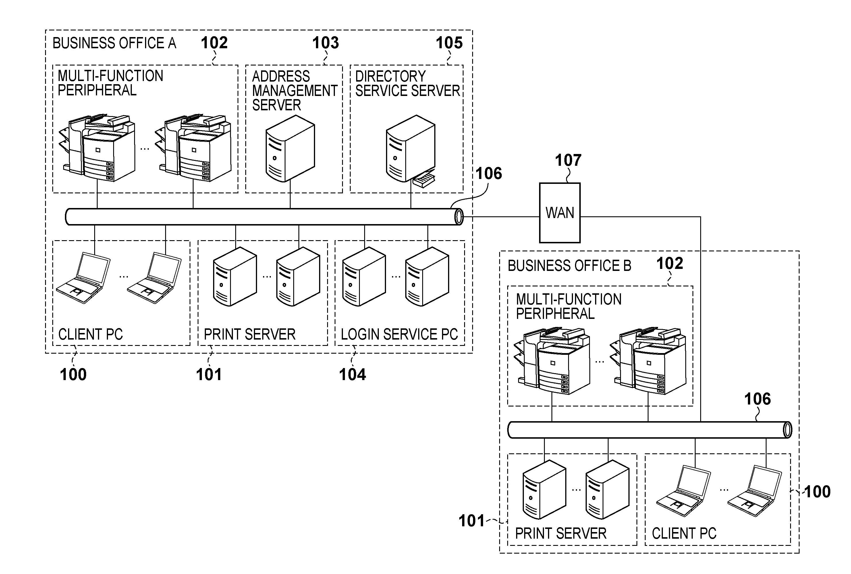
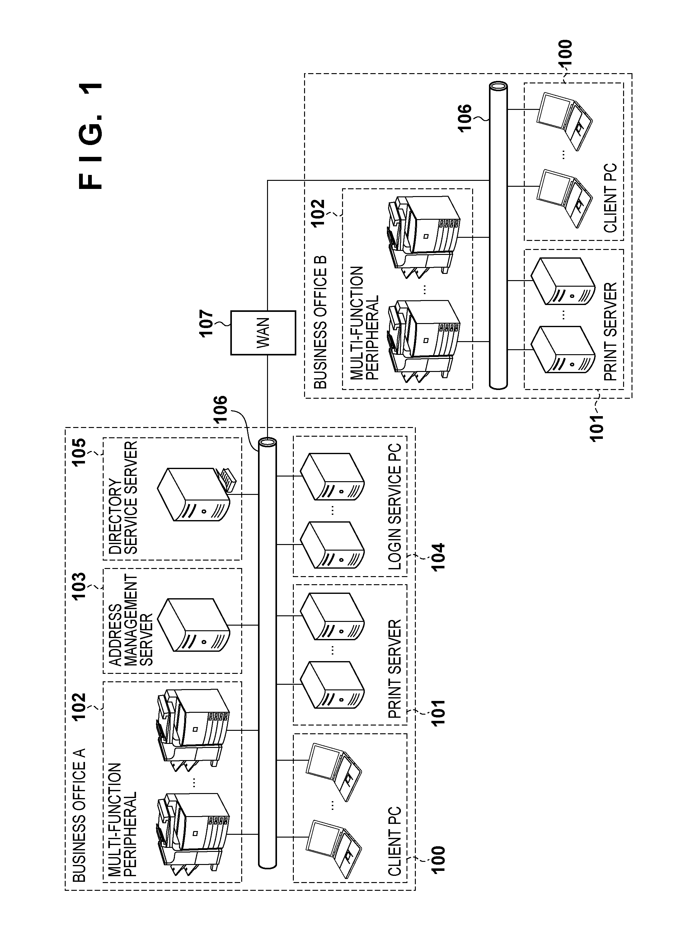
[0039]Embodiments of the present invention will now be described with reference to the accompanying drawings. FIG. 1 is a view exemplifying the configuration of a printing system to which an information processing apparatus, print server, address management server, and printing apparatus according to the present invention are applicable. Like “business office A” in FIG. 1, the printing system of the embodiment is configured by connecting one or a plurality of client PCs 100, one or a plurality of print servers 101, one or a plurality of multi-function peripherals 102, an address management server 103, one or a plurality of login service PCs 104, and a directory service server 105 via a local area network (LAN) 106.

[0040]A virtual printer driver is installed in the client PC 100. The virtual printer driver generates a print job of an intermediate format independent of a specific multi-function peripheral based on data received from a client application, and transm...

second embodiment

[0151]In the first embodiment, a PDL job is saved in the save area 304 of the multi-function peripheral 102. However, some multi-function peripherals do not have the save area. Hence, a system which uses an external memory 211 of a print server 101 as the save area will be described with reference to FIG. 17 and the flowchart of FIG. 18. In the second embodiment, the external memory 211 of the print server 101 shown in FIG. 1 will be referred to as the save area 211.

[0152][Pull Print Processing Sequence]

[0153]Processes in 1-1 to 2-10 in FIG. 17 are the same as those in FIG. 4, and a description thereof will not be repeated. However, when a job management service 403 issues a save instruction to the printer driver 408, the destination of save by a printer driver 408 is the save area211 ensured in the print server 101. The user selects a print job via the operation panel of a multi-function peripheral 102, and designates a change of print setting information and printing. In accordanc...

third embodiment

[0167]In the first embodiment, after the printer driver 408 is installed, the job management service 403 causes the printer driver 408 to perform PDL conversion using an EMFSPOOL print job and metadata. However, no search method has been designated for the job management DB 404, so the order of transmission to the printer driver 408 has not been determined. When many jobs are registered in the job management DB 404, saving all jobs may waste the save area more than necessary. To prevent this, the job search method for the job management service 403 and the maximum number of jobs to be saved in the save area need to be determined. The job search method and maximum job save count setting method will be described with reference to FIG. 19 and the flowchart of FIG. 20.

[0168][Example of Save Setting Window]

[0169]FIG. 19 is a schematic view exemplifying a setting window regarding save of a job management service 403 running on a print server 101 shown in FIG. 1. This setting is assumed to...


PUM


Abstract

A print server which communicates with an information processing apparatus including a virtual printer driver that generates a print job of an intermediate format independent of a printing apparatus, and a printing apparatus, comprises: a storage unit configured to store the print job of the intermediate format received from the information processing apparatus; a conversion unit configured to convert the print job of the intermediate format stored in the storage unit into a first PDL print job printable by the printing apparatus by using a printer driver of the printing apparatus; and a transmission unit configured to transmit the first PDL print job to save the first PDL print job converted by the conversion unit in the printing apparatus.

Description

BACKGROUND OF THE INVENTION[0001]1. Field of the Invention[0002]The present invention relates to a printing system, printing method, print server, control method, and computer-readable medium for performing pull print control.[0003]2. Description of the Related Art[0004]There has conventionally been proposed a so-called “pull print” printing system capable of outputting print data from a printing apparatus when the user issues a print request to the printing apparatus for print data temporarily stored in a server (see, for example, Japanese Patent No. 4033857). In printing from an application, the user can output print data not from a specific printing apparatus but from a printing apparatus of his choice.[0005]As a re-printing method for a printout the user did not intend, the following system is proposed (see, for example, Japanese Patent Laid-Open No. 2007-304881). More specifically, the UI (User Interface) of a printer driver running on a client PC is displayed on the panel of a...

Claims


Application Information

Patent Timeline
IPC IPC(8): G06F3/12
CPCG06F3/1205G06F3/1222G06F3/1238G06F3/1288G06F3/1247G06F3/1258G06F3/1267G06F3/1245
Inventor SUZUKI, SHINYA
Owner CANON KK
Learn More