
Fixed-focus lens

a fixed-focus lens and lens body technology, applied in the field of lenses, can solve the problems of image aberration, large overall size of the lens, and large increase in the fabrication cost of the lens, so as to achieve optimal imaging quality, reduce aberration, and large aperture

Active Publication Date: 2012-04-05
YOUNG OPTICS
View PDF0 Cites 16 Cited by
  • Summary
  • Abstract
  • Description
  • Claims
  • Application Information

AI Technical Summary

Benefits of technology

[0008]Accordingly, the invention is directed to a fixed-focus lens which has a lower fabrication cost and better optical characteristics than convention.
[0011]As described above, an embodiment of the invention offers at least one of following advantages or functions. Because according to an embodiment of the invention, the fixed-focus lens has two aspheric lenses and the overall structure of the fixed-focus lens satisfies aforementioned conditions, the fixed-focus lens has a large aperture and reduced aberration such that an optimal imaging quality is achieved. In addition, because according to an embodiment of the invention, the fixed-focus lens adopts fewer lenses and offers a simple focusing technique, both the structure and the assembly of the fixed-focus lens are simplified, and the fabrication cost of the fixed-focus lens is reduced.

Problems solved by technology

Image aberration has always been a major problem in the design of lenses with large apertures (for example, with their f-numbers smaller than 2).
However, because this lens is composed of 10 lenses and the total length of the lens is over 75 mm, the overall size of the lens is very large.
Because the lenses in foregoing lens are grouped into three lens groups and the lens focuses by moving the second lens group, the fabrication cost of the lens is greatly increased.

Method used


Image

  • Fixed-focus lens
  • Fixed-focus lens
  • Fixed-focus lens

Examples


first embodiment

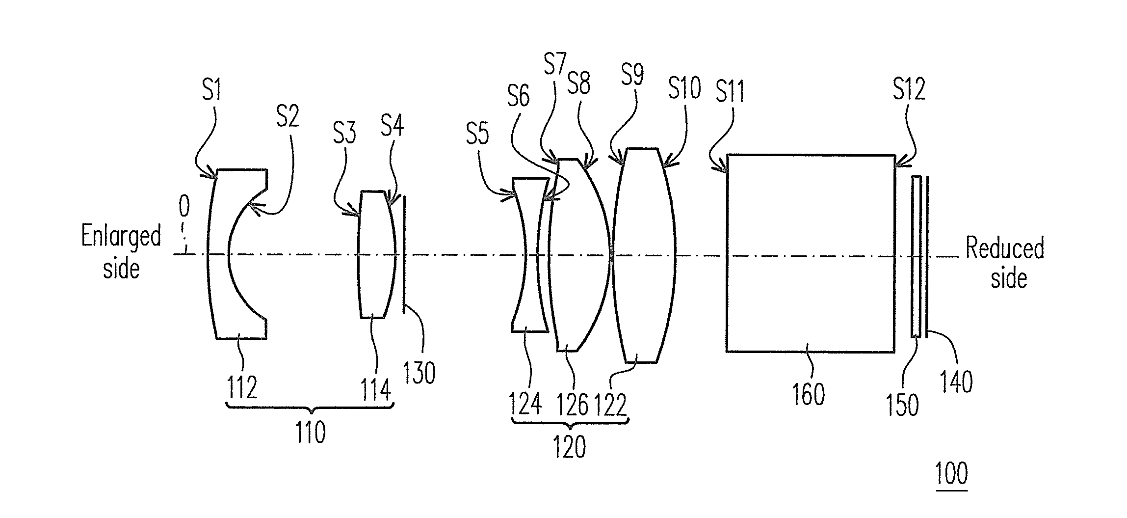
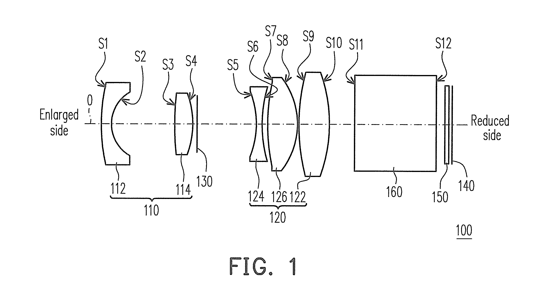
[0037]FIG. 1 is a structure diagram of a fixed-focus lens according to the first embodiment of the invention. Referring to FIG. 1, in the present embodiment, the fixed-focus lens 100 is disposed between an enlarged side and a reduced side and includes a first lens group 110 and a second lens group 120 sequentially arranged from the enlarged side to the reduced side. The first lens group 110 includes a lens 112, wherein the lens 112 is an aspheric lens. The second lens group 120 has a positive dioptre and is disposed between the first lens group 110 and the reduced side. The second lens group 120 includes a lens 122, wherein the lens 122 is an aspheric lens.

[0038]In the present embodiment, the fixed-focus lens 100 focuses by moving the first lens group 110 and the second lens group 120, and the fixed-focus lens 100 satisfies 0.1100, f1 is the effective focal length (EFL) of the first lens group 110, f2 is the EFL of the second lens group 120, L is the total length of the fixed-focus ...

second embodiment

[0052]FIG. 3 is a structure diagram of a fixed-focus lens according to the second embodiment of the invention. Referring to FIG. 3, in the present embodiment, the fixed-focus lens 200 is disposed between an enlarged side and a reduced side and includes a first lens group 210 and a second lens group 220 sequentially arranged from the enlarged side to the reduced side. The first lens group 210 includes a lens 212, wherein the lens 212 is an aspheric lens. The second lens group 220 has a positive dioptre and is disposed between the first lens group 210 and the reduced side. The second lens group 220 includes a lens 222, wherein the lens 222 is an aspheric lens. The fixed-focus lens 200 focuses by moving the first lens group 210 and the second lens group 220.

[0053]In the present embodiment, the lens 222 has a negative dioptre, and the lens 222 is a lens in the second lens group 220 that is closest to the aperture diaphragm 130. Besides, the fixed-focus lens 200 satisfies 0.2|f / f1|200, f...

third embodiment

[0064]FIG. 5 is a structure diagram of a fixed-focus lens according to the third embodiment of the invention. Referring to FIG. 5, in the present embodiment, the fixed-focus lens 300 is disposed between an enlarged side and a reduced side and includes a first lens group 310 and a second lens group 320 sequentially arranged from the enlarged side to the reduced side. The first lens group 310 includes a lens 312, wherein the lens 312 is an aspheric lens. The second lens group 320 has a positive dioptre and is disposed between the first lens group 310 and the reduced side. The second lens group 320 includes a lens 322, wherein the lens 322 is an aspheric lens. The fixed-focus lens 300 focuses by moving the first lens group 310 and the second lens group 320.

[0065]In the present embodiment, the lens 322 has a negative dioptre, and the lens 322 is a lens in the second lens group 320 that is closest to the aperture diaphragm 130. Besides, the fixed-focus lens 300 satisfies 0.2300, f1 is th...


PUM


Abstract

A fixed-focus lens disposed between an enlarged side and a reduced side is provided. An f-number of the fixed-focus lens is smaller than or equal to 2. The fixed-focus lens includes a first lens group and a second lens group. The first lens group includes a first lens, wherein the first lens is an aspheric lens. The second lens group, disposed between the first lens group and the reduced side, has a positive dioptre. The second lens group includes a second lens, wherein the second lens is an aspheric lens. The fixed-focus lens focuses by moving the first and the second lens group and satisfies 0.1<|f / f1|<1, 0.2<|f / f2|<1.5, and 1.5<L / BEL<3.5, where f, L, and BFL are respectively a focal length, a total length, and a back focal length of the fixed-focus lens, and f1 and f2 are respectively an effective focal length of the first and the second lens group.

Description

CROSS-REFERENCE TO RELATED APPLICATION[0001]This application claims the priority benefit of Taiwan application serial no. 99133373, filed Sep. 30, 2010. The entirety of the above-mentioned patent application is hereby incorporated by reference herein and made a part of this specification.BACKGROUND OF THE INVENTION[0002]1. Field of the Invention[0003]The invention generally relates to a lens, and more particularly, to a fixed-focus lens.[0004]2. Description of Related Art[0005]An existing small light emitting diode (LED) projectors usually produces a brightness of merely 100 lumens. To increase the brightness of a small LED projector without increasing the power of LED, a lens with a large aperture has to be adopted to increase the light utilization efficiency.[0006]Image aberration has always been a major problem in the design of lenses with large apertures (for example, with their f-numbers smaller than 2). One technique for resolving this problem is to adopt aspheric lenses. For ...

Claims


Application Information

Patent Timeline
Patent Type & Authority Applications(United States)
IPC IPC(8): G02B13/18
CPCG02B13/18
Inventor TSENG, CHIEN-HSIUNGCHOU, YU-HUNGCHEN, KAI-YUNLIN, YING-HSIU
Owner YOUNG OPTICS
Learn More