
Solar-Powered Self-Watering Planter Insert

a planter insert and solar energy technology, applied in renewable energy machines, instruments, process and machine control, etc., can solve the problems of not revealing a height-adjustable riser, plant maintenance can be a lot, etc., to facilitate the removal of the tray, facilitate the replenishment of the reservoir, and eliminate the daily labor

Inactive Publication Date: 2012-04-05
CONRAD JR MICHAEL L
View PDF7 Cites 14 Cited by
  • Summary
  • Abstract
  • Description
  • Claims
  • Application Information

AI Technical Summary

Benefits of technology

[0013]It is the primary object of this invention to provide a self-contained, solar-powered, and self-watering insert for planters that eliminates the daily labor that would otherwise be needed to keep container-grown plants and flowers properly irrigated. It is also an object of this invention to provide a self-watering insert for planters that discourages unauthorized access to its pump and controller / timer, when located in public places. A further object of this invention is to provide a self-watering insert for planters that has an option for remote solar power generation, if the selected location of its supporting planter does not have adequate sun exposure for battery recharging. It is a further object of this invention to provide a self-watering insert for planters that has facilitated means for reservoir replenishment without movement of plants or their growth / support medium. It is also an object of this invention to provide a self-watering insert for planters that has facilitated means for tray removal from the supporting planter, and re-installation into its position of use. A further object of this invention is to provide a self-watering insert for planters that has a tray construction allowing fluid to pass through it and enter the reservoir underneath it for recycling. It is also an object of this invention to provide a self-watering insert for planters which has a tray constructed for holding one or more plant growth pots, or in the alternative may contain growth / support medium distributed directly into the tray for plant support. It is a further object of this invention to provide a self-watering insert for planters that has irrigation means that evenly distributes fluid to differing portions of the tray. In addition it is an object of this invention to provide a self-watering insert for planters with an option that allows alternative positioning of the riser so that a single plant can be centered relative to an associated planter.
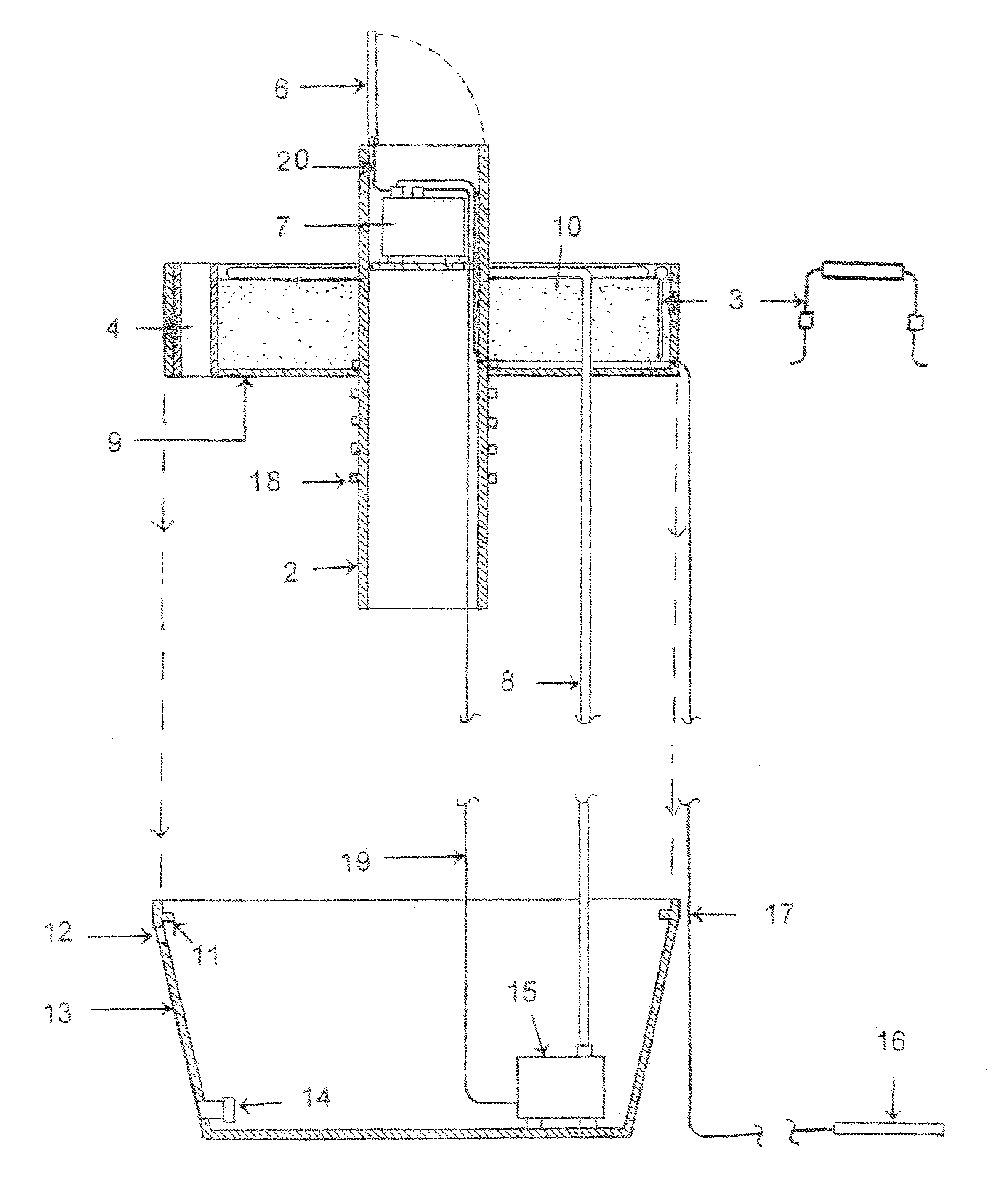
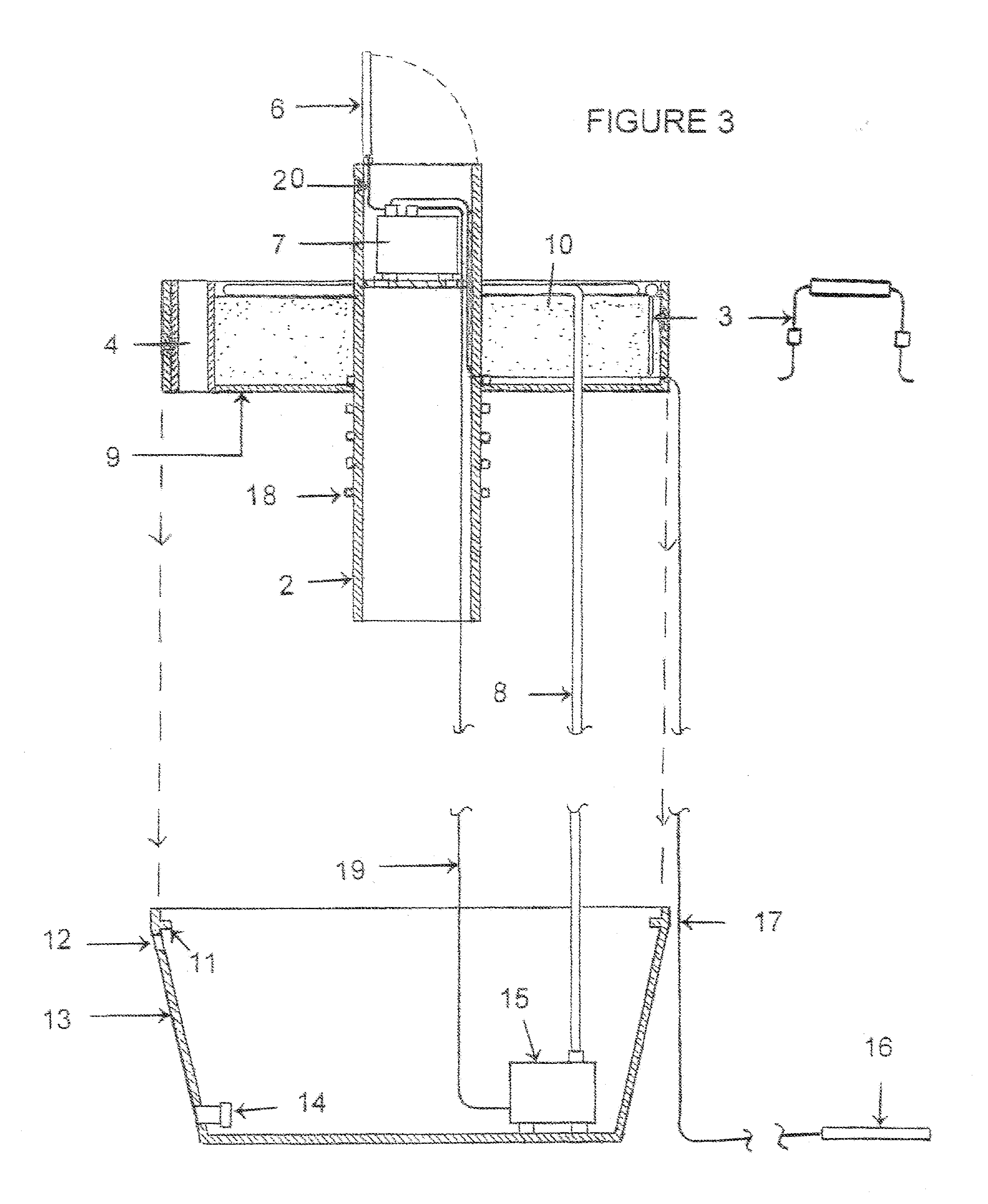
[0014]The present invention, when properly made and used, provides a self-contained insert for use with a planter to provide self-watering of a plant or plants positioned on or above a perforated tray that is removably supported over a reservoir, to eliminate the daily labor that would otherwise be needed to keep container-grown plants and flowers properly irrigated. Multiple sizes and shapes of insert are contemplated, and although its reservoir needs periodic fluid replenishment, no municipal power or water supply connections are needed for proper function of the present invention insert. The present invention's reservoir houses a submersible pump, and water or nutrient solution that is distributed to the plants in the tray by a drip line connected to the pump. The fluid then filters downwardly through the growth or support medium, with excess fluid moving through perforations in the tray and back into the reservoir, where it is recycled. After the present invention's reservoir is lowered into an independent planter typically of comparable size, the present invention tray is lowered via handles onto a supporting lip inside the reservoir. The bottom of the present invention tray is perforated, and it holds one or more potted plants, or plant / plants rooted in a growth or support medium distributed directly into the tray.
[0015]The present invention's tray and reservoir are generally configured and sized to substantially fill an associated planter, with the topmost portion of the tray typically positioned below the planter's top edge, but not limited thereto. The size of the pump is also variable, and selected according to the volume of water contemplated for delivery during each watering cycle via a drip line to a plant or plants supported by the tray. A height-adjustable riser is also supported by the tray, which houses a controller / timer / batteries, and may optionally support a solar panel unit. The riser typically extends above the top edge of the associated planter, particularly when it supports a solar panel unit so that it can be raised as needed above new plant growth and continue to generate power for pump and controller / timer function. The present invention's controller / timer is programmable to set the desired frequency and duration of fluid delivery to the drip line situated above the tray. Should additional fluid be needed in the reservoir, the insert's tray has a fill-hole opening through it so that tray removal is not required. In addition, the reservoir also preferably has two side openings, a higher one that reduces the likelihood of fluid in the reservoir moving upwardly through the tray and growth / / support medium where it could cause over-watering of plants, and a lower drain opening that during reservoir use is preferably sealed with a threaded cap.

Problems solved by technology

People enjoy plants, but depending upon their location, plants can require a lot of maintenance.
Furthermore, the Olson invention does not disclose a height-adjustable riser, or a self-contained system that allows excess water from a drip line to pass through perforations in a plant tray into a reservoir below for recycling.

Method used


Image

  • Solar-Powered Self-Watering Planter Insert
  • Solar-Powered Self-Watering Planter Insert
  • Solar-Powered Self-Watering Planter Insert

Examples


Embodiment Construction

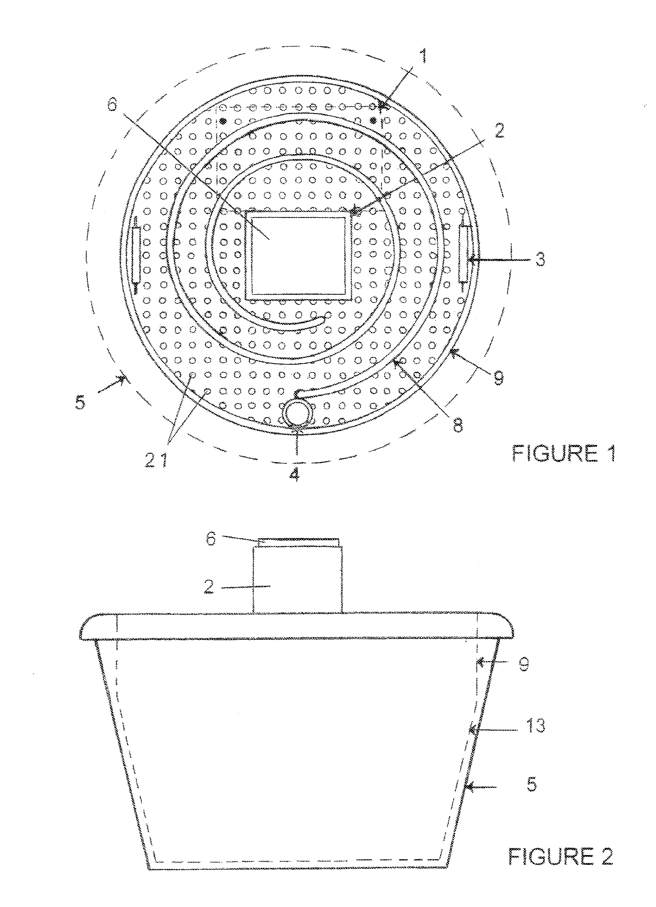
[0021]While FIGS. 1-3 show the most preferred embodiment of the present invention planter insert for self-watering of container-grown plants (not shown), it is to be understood that many variations in the present invention are possible and also considered to be a part of the invention disclosed herein, even though such variations are not specifically mentioned or shown. As a result, a reader should determine the scope of the present invention by the appended claims.

[0022]FIG. 1 is a top view of the tray 9 and drip line 8 used as a part of the most preferred embodiment of the present invention, which also shows two handles 3 placed in opposed positions to one another near the perimeter of tray 9. While FIG. 1 shows a configuration of handles 3 usable as a part of the most preferred embodiment of the present invention, the size, configuration, and positioning of handles 3 used to lift tray 9 from its usable position and reinstall it, may be different from that shown. It is also prefer...


PUM


Abstract

A self-contained insert for use with a planter to provide self-watering of container-grown plants. It has a perforated tray supported over a reservoir that contains a submersible pump, and water or nutrient solution. Plants may be in pots supported by the tray, or plant roots may be in a growth or support medium distributed directly into the tray. A height-adjustable riser supported by the tray houses the pump's controller / timer / battery. A drip line connected to the pump distributes fluid from the reservoir to plants in the tray. Solar power is used for pump operation, and may be derived from a unit secured to the riser, or a unit positioned remotely from the reservoir and tray. No municipal power or water supply connections are needed for insert function. Applications include, but are not limited to, use for daily watering of plants in residential homes, commercial buildings, hotels, convention centers, and college campuses.

Description

CROSS-REFERENCES TO RELATED APPLICATIONS[0001]None.BACKGROUND[0002]1. Field of the Invention[0003]This invention relates to apparatus and systems used to provide water / fluids to container-grown plants, specifically to an insert comprising a perforated tray and a reservoir member that in combination are used within a planter to provide self-contained, self-watering of a plant or plants positioned on or above the tray, while the tray is removably supported upon a lip inwardly depending from the upper portion of the reservoir. The present invention insert is self-contained, with power for its submersible pump and controller / timer being provided by a solar panel unit, and no municipal power or water supply connections are needed for its function. Plants may be in pots supported by the tray, or plant roots may be established in a growth or support medium distributed within the tray. Water or nutrient solution from its reservoir is delivered to the plants in the tray by a drip line in flu...

Claims


Application Information

Patent Timeline
Patent Type & Authority Applications(United States)
IPC IPC(8): G05D7/06
CPCA01G9/02A01G27/02A01G27/001A01G27/00A01G27/003Y02P60/12
Inventor CONRAD, JR., MICHAEL L.
Owner CONRAD JR MICHAEL L
Learn More