Decoupling controller for power systems

a power system and controller technology, applied in the direction of process and machine control, material dimension control, instruments, etc., can solve the problems of voltage and frequency on the microgrid bus to oscillate, increase the reactive power delivered, voltage to change,

Active Publication Date: 2012-04-05
OSLSOFT INC
View PDF8 Cites 39 Cited by
  • Summary
  • Abstract
  • Description
  • Claims
  • Application Information

AI Technical Summary

Benefits of technology

[0011]In yet another aspect, the present invention provides a method for bumpless and balanceless power transfer switching between a microgrid and a macrogrid when disconnecting or connecting to the macrogrid. The method includes switching a 2×2 decoupled controller to manual mode, adjusting (i.e., accelerating or decelerating) a speed of a generator of the microgrid so that its output absolute voltage angle matches the absolute voltage angle of the macrogrid. When the difference is zero, the switching is made. Similarily, before the 2×2 controller is turned on, the angle difference between the microgrid and the macrogrid is driven to zero by adjusting (i.e., accelerating or decelerating) the generator. When the angle difference is zero, the 2×2 decoupled control is turned to automatic mode. This method naturally results in a voltage phase angle difference of zero, at which point the power between the macrogrid and microgrid may be switched. This method exceeds all of the IEEE 1547 standards for switching distributed generation sources into or out of the macrogrid.

Problems solved by technology

However, increasing the real power delivery will also increase the reactive power delivered.
This change in reactive power will cause the voltage to change.
Thus, the two controllers fight against each other, causing the voltage and frequency on the microgrid bus to oscillate.
This is then likely to trip the other sources in the microgrid and the entire system will fail.
Additionally, the oscillations have been misunderstood as being caused by load changes rather than being induced by the fighting controllers.

Method used


Image

  • Decoupling controller for power systems
  • Decoupling controller for power systems
  • Decoupling controller for power systems

Examples


Embodiment Construction

[0015]The principles of the present invention may be appreciated by first considering the behavior of the CERTS microgrid controller.

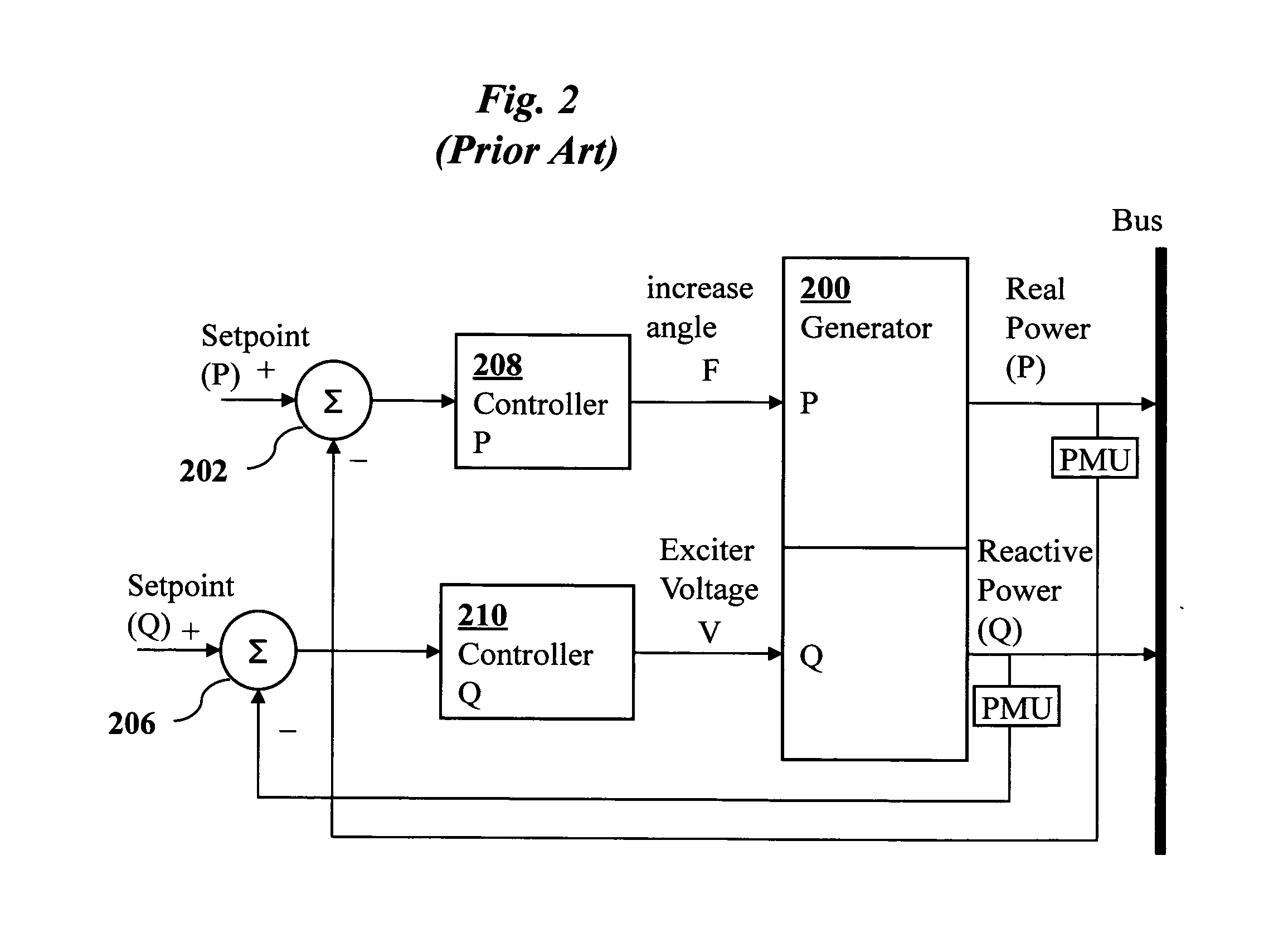
[0016]FIG. 2, for example, shows a prior art controller system for generator 200 with separate P and Q feedbacks to independent summation elements 202 and 206 and simple proportional-integral-derivative (PID) controllers 208 and 210. The derivative term is rarely, however, used since the oscillation between P and Q would be amplified by a derivative term in the standard controllers. Thus, the controllers are in effect PI controllers. The P and Q set points entering from the left of the figure are selected by the grid dispatcher to request specific amounts of real power P and reactive power Q (e.g., 100 MW real power and 10 MVAR reactive power). The dispatcher will request different set points depending on how the grid is responding to loads that cause distortions in voltage and frequency (e.g., if the grid frequency is low, the dispatcher requests a hi...


PUM


Abstract

A power system controller using a 2×2 decoupling controller, a model reference, and feedback with delay. Embodiments provide control of microgrid frequency F and voltage V. In addition, this technique can also be used to control the real and reactive power delivered from the microgrid to the connected macrogrid. The control engineering approach is the same in both cases, but the roles of the four variables involved are reversed.

Description

CROSS-REFERENCE TO RELATED APPLICATIONS[0001]This application claims priority from U.S. Provisional Patent Application 61 / 389,281 filed Oct. 4, 2010, which is incorporated herein by reference.FIELD OF THE INVENTION[0002]The present invention relates generally to electrical power system controllers. More specifically, it relates to improved microgrid power system controllers, and to improved wind farm and solar farm voltage and frequency controllers.BACKGROUND OF THE INVENTION[0003]Electricity is traditionally generated by large centralized power plants and transmitted long distances by power distribution systems. To reduce the need for long-distance power generation and dependence upon a few large centralized power plants, electricity is being generated more and more by smaller power generation facilities distributed throughout the macrogrid. Numerous private or municipal entities, for example, are operating modest size photovoltaic and wind power facilities. Such facilities, or a l...

Claims


Application Information

Patent Timeline
Patent Type & Authority Applications(United States)
IPC IPC(8): G06F1/28H02J3/04
CPCH02J3/1885H02J3/381Y02E40/32Y02E10/763H02J3/386H02J2300/28Y02E10/76Y02E40/30H02J3/48H02J3/50
Inventor WELLS, CHARLES H.
Owner OSLSOFT INC
Why Eureka
Try Eureka