Device with a heat exchanger and method for operating a heat exchanger of a steam generating plant

Active Publication Date: 2012-04-12
MARTIN GMBH FUR UMWELT UND ENERGIETECHNIK
View PDF10 Cites 5 Cited by
  • Summary
  • Abstract
  • Description
  • Claims
  • Application Information

AI Technical Summary

Benefits of technology

[0011]The object underlying the invention is therefore to further develop a generic device in such a manner that the desired temperature windows can be maintained for a longer period of time.

Problems solved by technology

Furthermore, deposits occur in the evaporator and in the superheaters, thus compromising the effectiveness of the heat exchangers.
During the first operating hours of such a plant, the heat exchangers still have a high effectiveness which however decreases during the operating time due to deposits.

Method used


Image

  • Device with a heat exchanger and method for operating a heat exchanger of a steam generating plant
  • Device with a heat exchanger and method for operating a heat exchanger of a steam generating plant
  • Device with a heat exchanger and method for operating a heat exchanger of a steam generating plant

Examples


Embodiment Construction

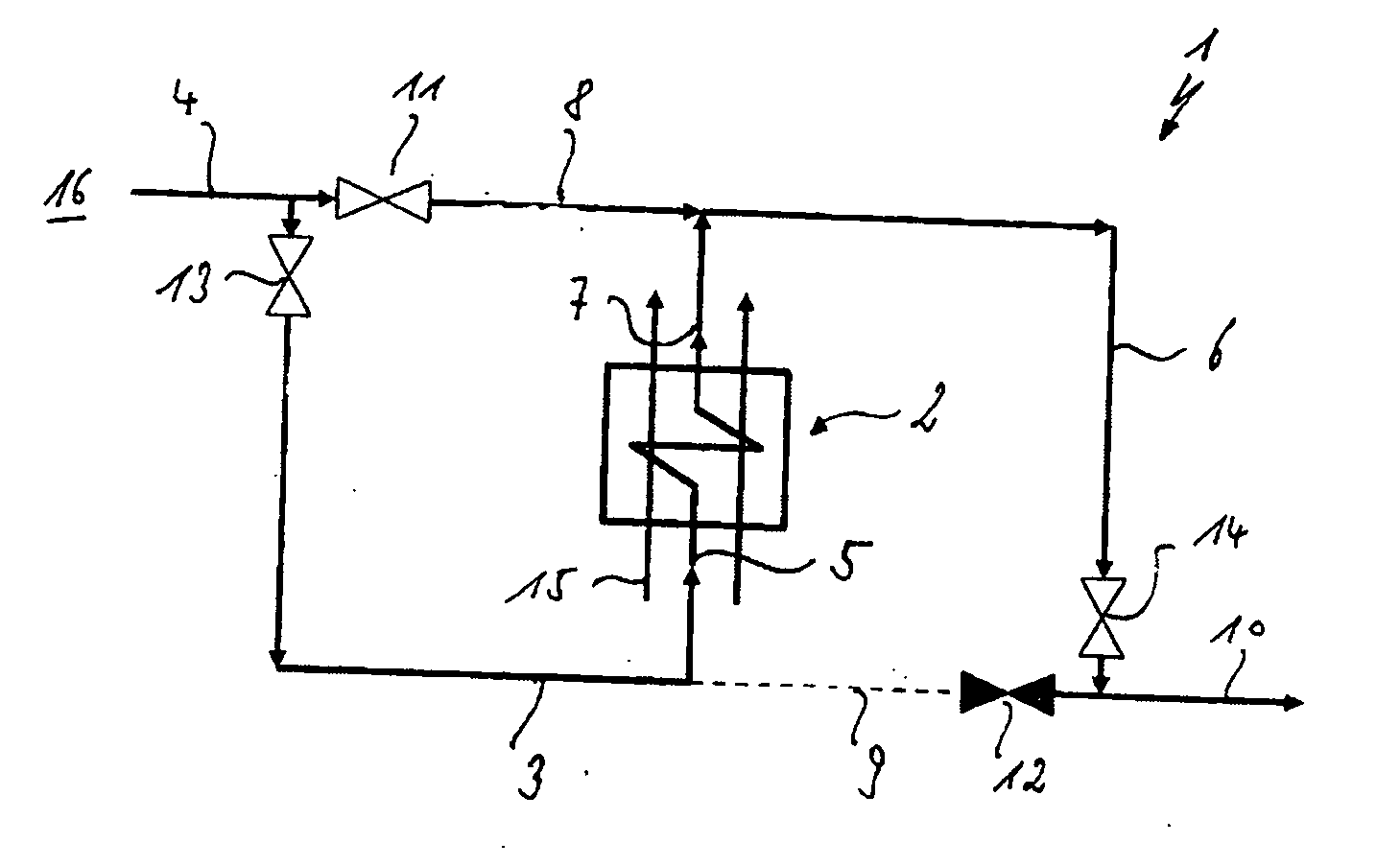
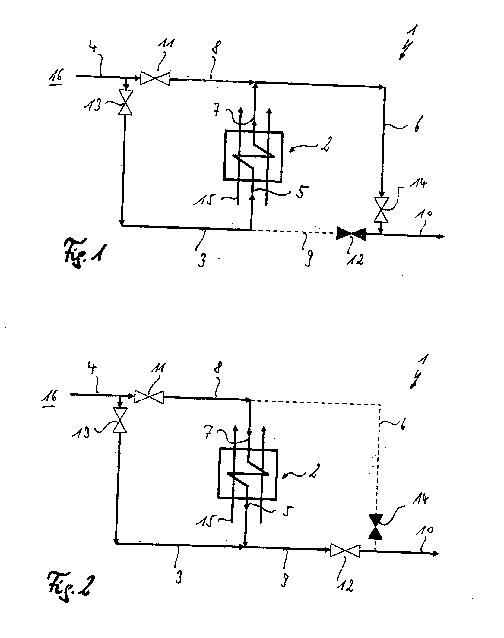
[0033]The device 1 shown in FIG. 1 consists substantially of a heat exchanger 2, which is supplied with a medium 16 via a feed pipe 3. This feed pipe 3 leads from a medium inlet 4 to the heat exchanger entrance 5. A discharge pipe 6 from the heat exchanger exit 7 is provided on the side facing away from the heat exchanger entrance. A first bypass 8 thereby leads from the medium inlet 4 to the discharge pipe 6 and a second bypass 9 leads from the feed pipe 3 to the medium outlet 10.

[0034]A first bypass valve 11 is provided between the medium inlet and the first bypass 8 and a second bypass valve 12 is provided between the second bypass 9 and the medium outlet 10. A feed pipe valve 13 is disposed in the feed pipe 3 and a discharge pipe valve 14 is provided in the discharge pipe 6.

[0035]In the present case, the second medium is a gas, the flow of which is indicated by the arrows 15. In the example shown in FIG. 1, the heat exchanger 2 thus operates in concurrent flow.

[0036]To this end,...


PUM


Abstract

A device with a heat exchanger with a feed pipe for a medium leading from a medium inlet to the heat exchanger entrance and with a discharge pipe leading away from the heat exchanger exit is characterized in that it has a first bypass from the medium inlet to the discharge pipe and a second bypass from the feed pipe to the medium outlet and valves, so that the medium can also flow from the heat exchanger exit to the heat exchanger entrance.

Description

CROSS REFERENCE TO RELATED APPLICATIONS[0001]Applicants claim priority under 35 U.S.C. §119 of German Application No. 10 2010 048 065.7 filed on Oct. 12, 2010 and under 35 U.S.C. §119(e) of United States Provisional Patent Application Serial No. 61 / 404,963 filed on Oct. 13, 2010, the disclosures of which are incorporated herein by reference.BACKGROUND OF THE INVENTION[0002]1. Field of the Invention[0003]The invention relates to a device with a heat exchanger with a feed pipe for a medium leading from a medium inlet to the heat exchanger entrance and with a discharge pipe leading away from the heat exchanger exit.[0004]2. The Prior Art[0005]Such type heat exchangers are needed in many applications. The transferred energy is thereby determined by the different temperatures of the media that are carried in the heat exchanger. Different control mechanisms are known for varying the volume flow of these media. Since it is frequently necessary to achieve certain medium temperatures without...

Claims


Application Information

Patent Timeline
IPC IPC(8): F28F27/00
CPCF22B1/18F28F27/02F22B15/00F22G1/02F22B31/08F22D1/02F22B31/00
Inventor MARTIN, JOHANNESVON RAVEN, ROBERTSEITZ, ALEXANDER
Owner MARTIN GMBH FUR UMWELT UND ENERGIETECHNIK
Why Eureka
Try Eureka