
Process for co2 capture using micro-particles comprising biocatalysts

Active Publication Date: 2012-05-17
SAIPEM SPA
View PDF6 Cites 30 Cited by
  • Summary
  • Abstract
  • Description
  • Claims
  • Application Information

AI Technical Summary

Benefits of technology

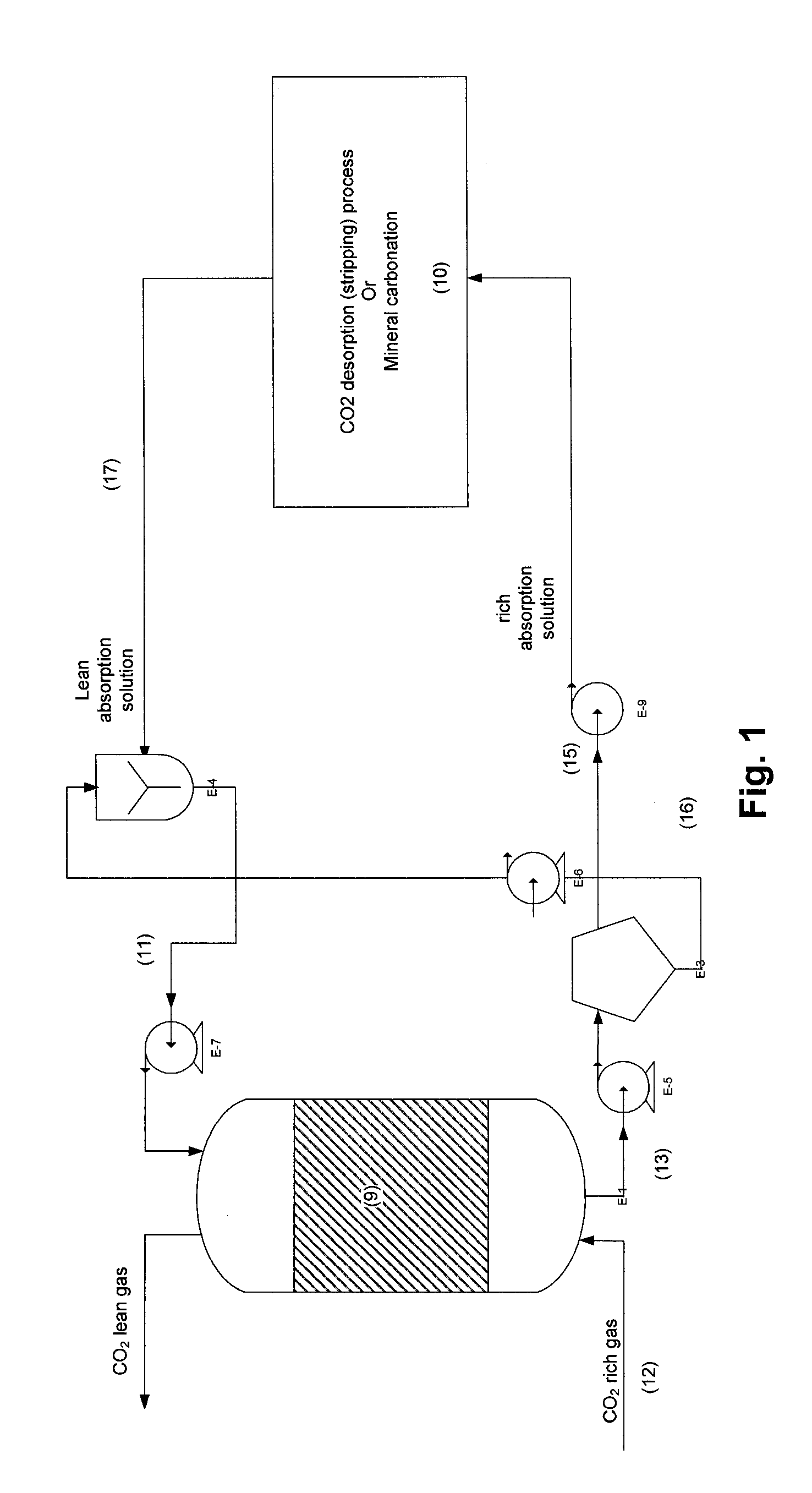
[0033]Managing and coordinating the size, concentration and biocatalytic activity of the micro-particles allows advantageous operation in CO2 capture processes.

Problems solved by technology

Both of these methods provide benefits but also some limitations.
Soluble enzyme brings the optimal enzyme impact, however it cannot be easily separated from the solution and if the enzyme is not robust to intense conditions such as those used in desorption operations, it will be denatured and the process will require high levels of continuous enzyme replacement.

Method used


Image

  • Process for co2 capture using micro-particles comprising biocatalysts
  • Process for co2 capture using micro-particles comprising biocatalysts
  • Process for co2 capture using micro-particles comprising biocatalysts

Examples


example 1

[0059]The micro-particle support material may be made of nylon, silica, silica gel, chitosan, polystyrene, polymethylmetacrylate, cellulose, magnetic particles, and other material known to be used for biocatalysts immobilization. The micro-particles may also be composed of a combination of different materials. For instance, the support may have a core composed of a material having different density or other properties compared to a different surface material which is provided for immobilization or entrapment of the enzymes. For example, the core of the support may be composed of a magnetic material to enable magnetic separation and the surface material may be polymeric such as nylon for supporting the enzyme. As noted above, in one embodiment the support material may be an aggregate of enzymes to form CLEA or CLEC. The micro-particles may each define an integral solid volume (e.g. a bead-like shape) or may comprise one or more apertures traversing the main volume of the particle (e....

example 2

[0061]An experiment was conducted in an absorption packed column. The absorption solution is an aqueous solution of methyldiethanolamine (MDEA) 4M. This absorption solution is contacted counter-currently with a gas phase with a CO2 concentration of 130,000 ppm. Liquid flow rate was 0.65 g / min and gas flow rate was 65 g / min corresponding to L / G of 10 (g / g). Gas and absorption solution were at room temperature. Operating pressure of the absorber was set at 1.4 psig. The column has a 7.5 cm diameter and a 50 cm height. Packing material is polymeric Raschig rings 0.25 inch. Three tests were performed: the first with no activator, the second with carbonic anhydrase immobilized to packing support and the third using carbonic anhydrase free in solution at a concentration of 0.5 g per liter of solution.

[0062]The results obtained showed that CO2 transfer rate or CO2 removal rate increased from 6 to 14 mmol CO2 / min with carbonic anhydrase immobilized onto the surface of Raschig rings. In the ...

example 3

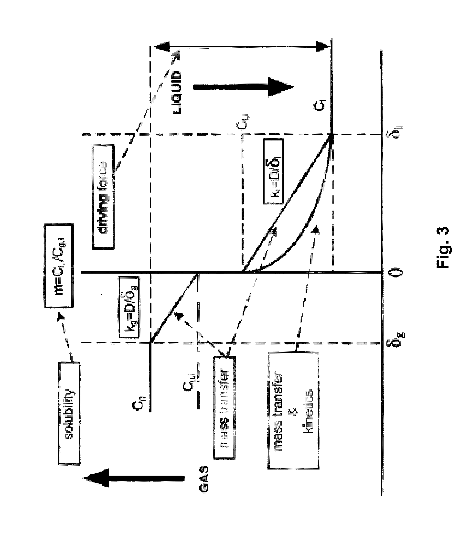
[0064]To further determine the impact of enzymatic micro-particles on CO2 absorption rate, tests were conducted in a hydration cell. This hydration cell reactor was designed and operated at set conditions to control the area of the interface between a gas phase, CO2, and a liquid phase in an absorption process. This device was used to evaluate impact of enzymatic micro-particles on the CO2 absorption rate in a given absorption solution. Tests were conducted as follows: a known volume of the unloaded absorption solution is introduced in the reactor; then a known mass of micro-particles is added to the absorption solution (micro-particles may or may not contain enzyme); a CO2 stream is flowed through the head space of the reactor and agitation is started; pH of the solution is measured as a function of time; then pH values are converted into carbon concentration in g C / L using a carbon concentration-pH correlation previously determined for the absorption solution; absorption rates are...


PUM

PropertyMeasurementUnit
Fractionaaaaaaaaaa
Fractionaaaaaaaaaa
Thicknessaaaaaaaaaa

Abstract

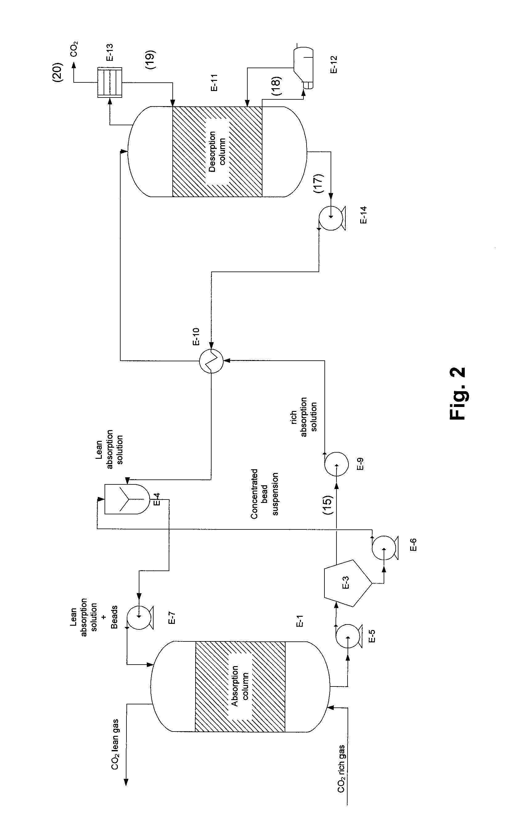
A process for capturing CO2 includes contacting a CO2-containing gas with an absorption mixture optionally within a packed reactor is provided. The absorption mixture includes a liquid solution and micro-particles. The micro-particles include a support material and biocatalyst supported by the support material and are sized and provided in a concentration such that the absorption mixture flows through the packed reactor and that the micro-particles are carried with the liquid solution to promote dissolution and transformation of CO2 into bicarbonate and hydrogen ions. The absorption mixture and micro-particles may be provided in an absorption reactor so as to be pumpable. Furthermore, a process for desorbing CO2 gas from an ion-rich aqueous mixture includes providing biocatalytic micro-particles and feeding the mixture to a desorption reactor, to promote transformation of the bicarbonate and hydrogen ions into CO2 gas and water.

Description

FIELD OF THE INVENTION[0001]The present invention relates generally to CO2 capture and more particularly to a process for CO2 capture using micro-particles comprising biocatalysts.BACKGROUND[0002]Increasingly dire warnings of the dangers of climate change by the world's scientific community combined with greater public awareness and concern over the issue has prompted increased momentum towards global regulation aimed at reducing man-made greenhouse gas (GHGs) emissions, most notably carbon dioxide. Ultimately, a significant cut in North American and global CO2 emissions will require reductions from the electricity production sector, the single largest source of CO2 worldwide. According to the International Energy Agency's (IEA) GHG Program, as of 2006 there were nearly 5,000 fossil fuel power plants worldwide generating nearly 11 billion tons of CO2, representing nearly 40% of total global anthropogenic CO2 emissions. Of these emissions from the power generation sector, 61% were fr...

Claims


Application Information

Patent Timeline
IPC IPC(8): B01D53/73C12S5/00C01B32/50
CPCB01D2252/504B01D53/1475B01D2255/804B01D2257/504Y02C10/04Y02C10/06B01D53/1425B01D53/1493B01D53/62B01D53/83B01D53/96B01D2251/306B01D2251/606B01D2252/20405B01D2252/20431B01D2252/20489B01D2252/20494B01D2252/205C01B31/20B01D2252/602C01B32/50Y02C20/40Y02P20/151B01D2251/304B01D2258/0283
Inventor FRADETTE, SYLVIEGINGRAS, JULIEVOYER, NORMANDCARLEY, JONATHANKELLY, GLENN R.CEPERKOVIC, OLIVERA
Owner SAIPEM SPA
Learn More