
Wrapping device

a wrapping device and cutting device technology, applied in the field of wrapping devices, can solve the problems of a large amount of time required for catching and clamping, the construction of many known clamping and cutting devices of wrapping devices is complex, and the space available in the known wrapping device for placing a clamping and cutting device, etc., and achieve the effect of simple design

Inactive Publication Date: 2012-04-19
LELY PATENT
View PDF16 Cites 14 Cited by
  • Summary
  • Abstract
  • Description
  • Claims
  • Application Information

AI Technical Summary

Benefits of technology

The invention provides a compact and reliable wrapping device for foil material that can be easily moved and positioned around an object. The device includes a frame, a carrying table for supporting the object, movable roll support devices for rotating foil material around the object, and a clamping and cutting device for clamping and cutting the foil material after wrapping it around the object. The carrying device can be pivoted to change the position of the clamping and cutting device, allowing for flexibility in the movement of the device. The clamping and cutting device is mounted on the carrying structure and can be moved with the carrying structure to different positions. The catch element of the clamping and cutting device can be moved from a catch position to a clamp position simultaneously with the carrying structure, making it easier to position the device. The catch element has a curved shape and can be oriented in different directions, making it easier to catch the foil material and position it in relation to the rolls of foil material during wrapping. The device is designed to provide a more efficient and compact solution for clamping and cutting foil material.

Problems solved by technology

At the same time little space is available in the known wrapping device to place a clamping and cutting device, in particular at a location in which the catch element can easily be moved into and out of the trajectory of the wrapping material during wrapping.
As a result, many known clamping and cutting devices of wrapping devices have a complex construction.
Furthermore, the time required performing the catching and clamping is relatively long.

Method used


Image

  • Wrapping device
  • Wrapping device
  • Wrapping device

Examples


Embodiment Construction

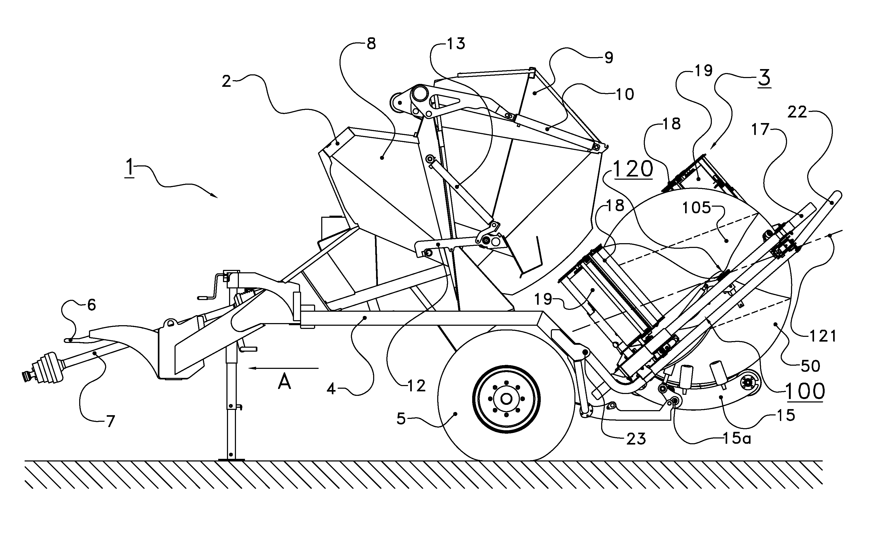
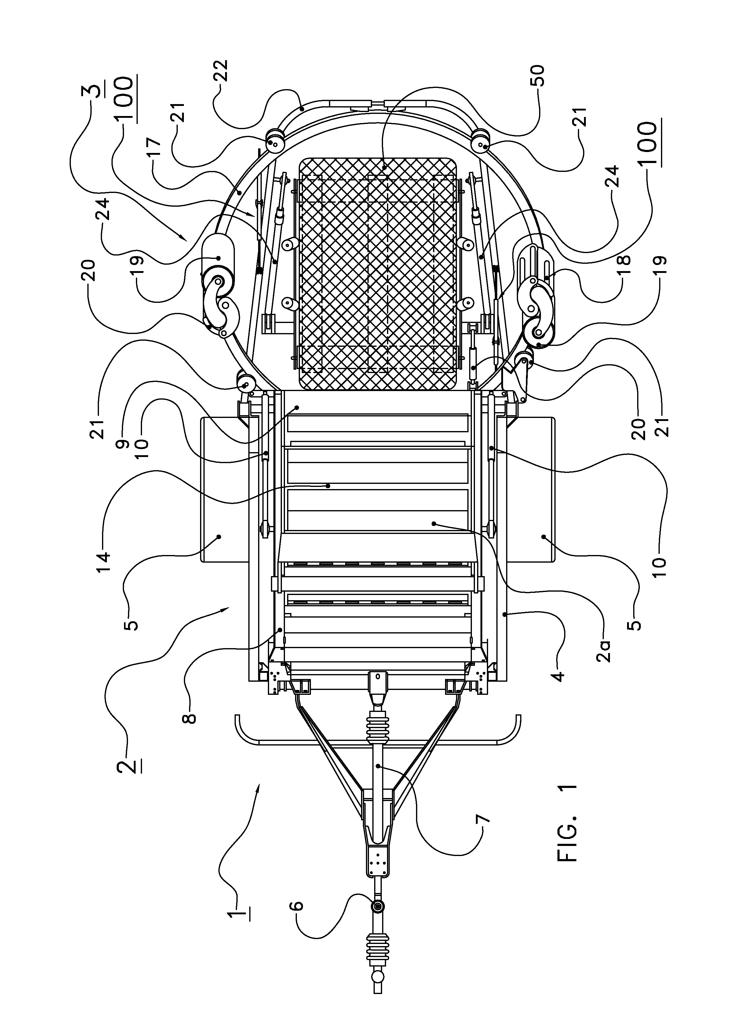
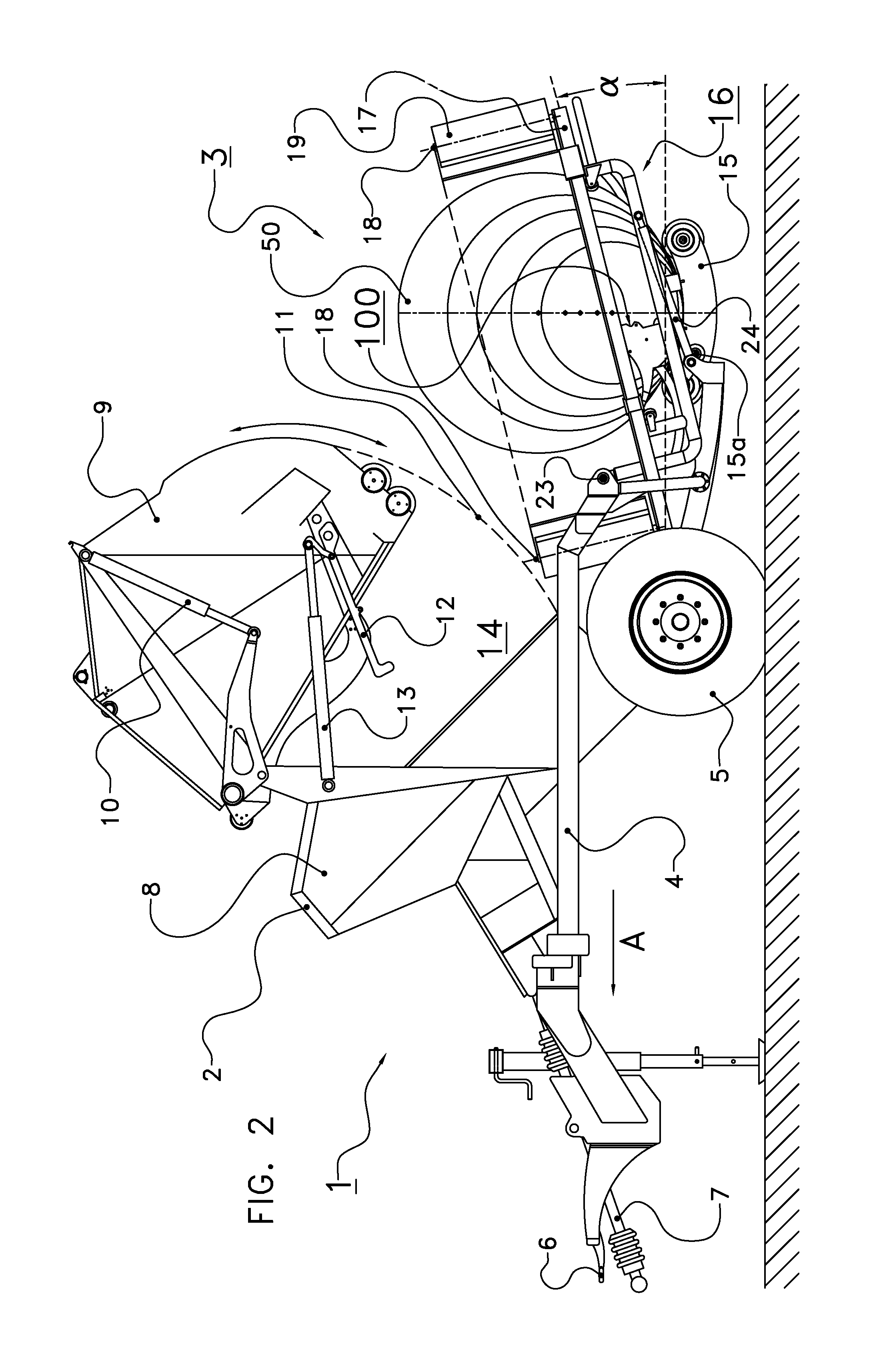
[0057]The following is a description of certain embodiments of the invention, given by way of example only and with reference to the drawings. FIG. 1 shows, in top view, an agricultural unit according to the invention which is generally indicated with the reference numeral 1. The agricultural unit 1 comprises a baling device 2 and a wrapping device 3, and is configured to form and wrap bales of crop material. FIG. 2 shows a side view of the agricultural unit 1 of FIG. 1 during wrapping of a bale, as will be described hereinafter.

[0058]The baling device 2 and the wrapping device 3 are mounted on a frame 4 which is supported by a pair of wheels 5. The front end 6 of the frame 4 is configured to be connected to a tractor, or other machinery configured to move the agricultural unit in an intended driving direction, indicated by an arrow A. A drive shaft 7 is provided to couple the agricultural unit 1 to a drive mechanism, for instance a drive shaft of a tractor.

[0059]The wrapping device...


PUM

PropertyMeasurementUnit
angleaaaaaaaaaa
angleaaaaaaaaaa
diameteraaaaaaaaaa

Abstract

The invention relates to a wrapping device to wrap an object in foil material including a frame, a wrapping table mounted on the frame and configured to support the object during wrapping, one or more roll support devices to support one or more rolls of foil material to be rotated about the object during wrapping, a carrying structure mounted on the frame and configured to carry the one or more roll support devices, and a clamping and cutting device to clamp the foil material after wrapping of an object, and to cut the clamped foil material, wherein the clamping and cutting device is mounted on the carrying structure, and wherein the carrying structure is pivotable about a substantially horizontal pivot axis with respect to the frame.

Description

CROSS REFERENCE TO RELATED APPLICATIONS[0001]This application is a continuation-in-part of PCT application number PCT / NL2010 / 000068 filed on 15 Apr. 2010, which claims priority from Netherlands application number 1037003 filed on 29 May 2009, and a continuation-in-part of PCT patent application number PCT / NL2010 / 000075 filed 6 May 2010, which claims priority from Netherlands application number NL 1037000 filed on 29 May 2009. All aforementioned applications are hereby incorporated by reference in their entireties.BACKGROUND OF THE INVENTION[0002]1. Field of the Invention[0003]The present invention relates to a wrapping device for wrapping objects in foil material. In particular, the invention relates to a wrapping device for wrapping bales of crop material after a bale has been formed in a baling device. The baling device and wrapping device may be integrated in a single agricultural unit or be provided as two separate agricultural systems.[0004]2. Description of the Related Art[000...

Claims


Application Information

Patent Timeline
Patent Type & Authority Applications(United States)
IPC IPC(8): B65B11/00B65B41/00A01D39/00A01F15/07
CPCA01F15/071A01F2015/0735B65B11/04B65B53/00B65B27/125A01F2015/0725A01F2015/073B65B11/008B65B41/16B65B61/06
Inventor REIJERSEN VAN BUUREN, WILLEM JACOBUS
Owner LELY PATENT
Learn More