Power transformer condition monitor

a technology for condition monitors and power transformers, applied in the direction of transformer/inductance details, basic electric elements, electrical equipment, etc., can solve the problem of lack of sensors to determine the potential condition of transformers, and achieve the effect of reducing the number of different communication devices and communication addresses

Inactive Publication Date: 2012-04-19
MATTHEWS KENNETH R
View PDF20 Cites 35 Cited by
  • Summary
  • Abstract
  • Description
  • Claims
  • Application Information

AI Technical Summary

Benefits of technology

[0018]It is another object of the power transformer condition monitor for the monitor to have a localized board for multiple sensors. The localized board can have a large plurality of i

Problems solved by technology

They lacked any sensors to determine a pote

Method used


Image

  • Power transformer condition monitor
  • Power transformer condition monitor
  • Power transformer condition monitor

Examples


Embodiment Construction

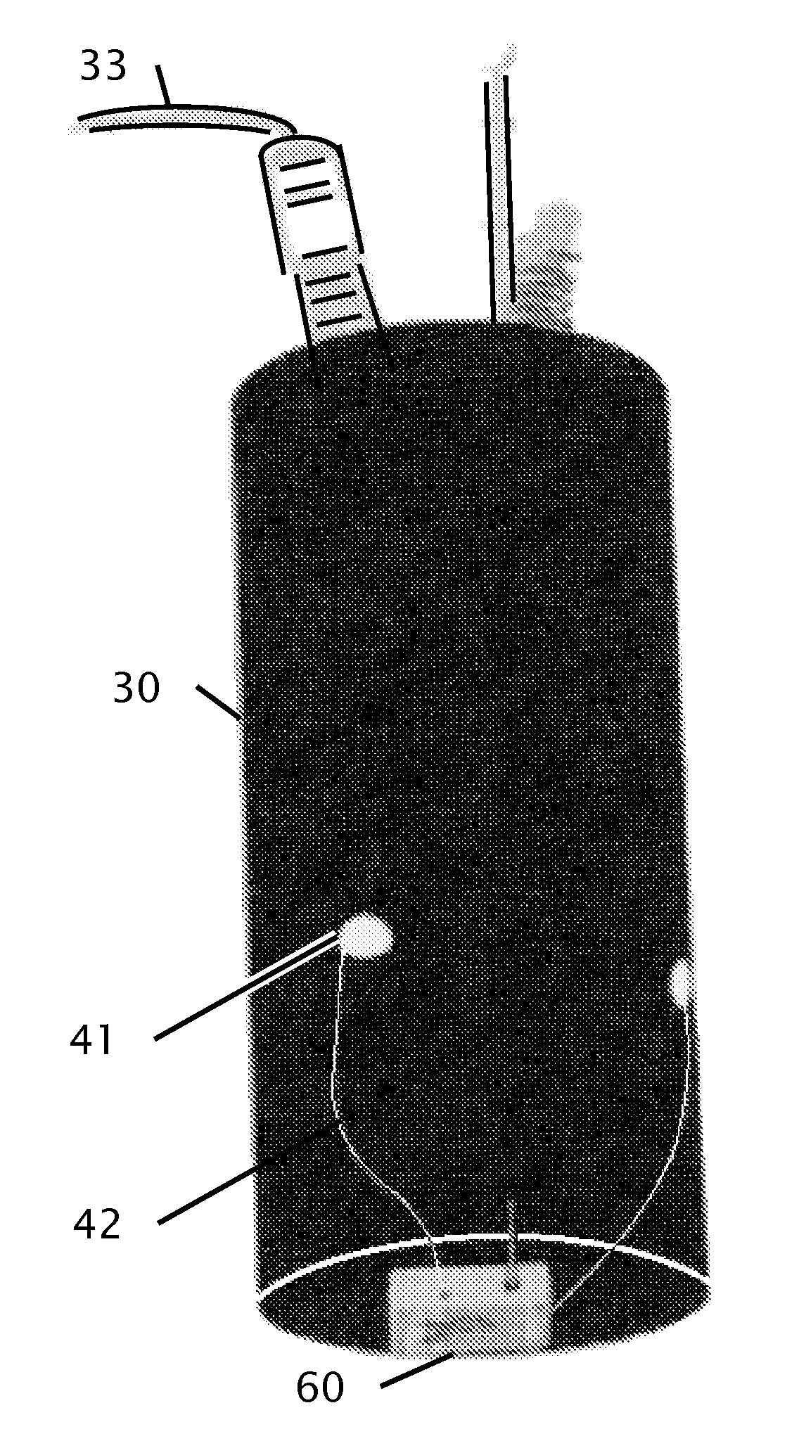
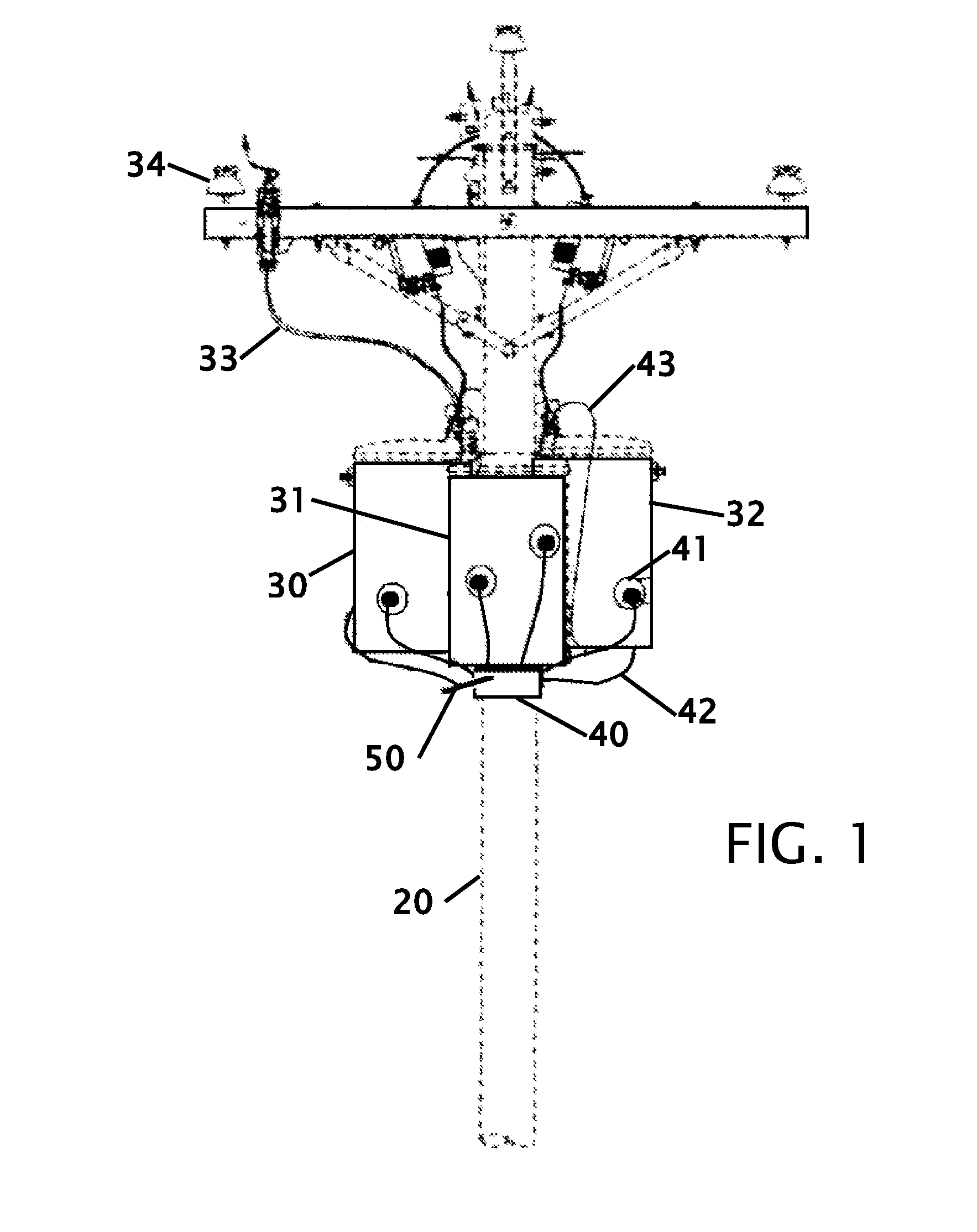
[0027]FIG. 1 shows a typical installation of multiple power transformers with a condition monitor. The condition monitor 40 is shown attached to the underside of the transformers 30, 31 and 32 that are mounted on a power pole 20. The transformers receive electrical power from wires that are secured to insulators 34 that connect 33 to the transformer(s). The condition monitor 40 deploys sensors 41 on transformers 30, 31 and 32 that are magnetically attached to the transformer(s) to detect temperature readings in increments that are set by the operator wirelessly through the network. Current units are capable of handling a minimum of six (6) plug-in sensors with an internal sensor that are wired 42 to the condition monitor 40 and used to monitor temperature of the transformer(s) along with the ambient air temperature. Additional sensors can be wired to the power connection of the transformer primary and or secondary power connection 43 to measure voltage, current or power factor. The ...


PUM


Abstract

Improvements in a power transformer condition monitor are disclosed with this application. The monitor operates with older existing transformers with and without integrated sensors and allows the device to determine the condition of transformers. The sensors monitor one or a multiple of voltage, current, temperature and or power factor. Thermal sensors are magnetically attached to the exterior of the power transformer. Voltage and current sensors are connected to the primary and secondary conductive wires. The monitor can be parasitically powered to operate with limited battery size. The only use of batteries or storage capacitors is when the supply voltage is lost. The monitor uses a localized board can have a large plurality of inputs for sensors. This allows multiple transformers to be locally connected to the monitor and thereby reduce the number of different communication devices and communication addresses over a Mesh, GPRS Cell network link network.

Description

CROSS REFERENCE TO RELATED APPLICATION[0001]This application claims the benefit of Provisional Application Ser. No. 61 / 393,700 filed Oct. 15, 2010 the entire contents of which is hereby expressly incorporated by reference herein.STATEMENT REGARDING FEDERALLY SPONSORED RESEARCH OR DEVELOPMENT[0002]Not ApplicableTHE NAMES OF THE PARTIES TO A JOINT RESEARCH AGREEMENT[0003]Not ApplicableINCORPORATION-BY-REFERENCE OF MATERIAL SUBMITTED ON A COMPACT DISC[0004]Not ApplicableBACKGROUND OF THE INVENTION[0005]1. Field of the Invention[0006]This invention relates to improvements in a monitor for power transformers. More particularly, the present Power Transformer Condition Monitor can be connected to an existing power transformer that was not built with monitoring capability. Sensors are magnetically connected to the outside surface of the transformer and are electrically or inductively connected to the power lines to monitor the power transformer. The information is stored and or transmitted ...

Claims


Application Information

Patent Timeline
IPC IPC(8): H01F27/00
CPCH01F2027/406H01F27/402
Inventor MATTHEWS, KENNETH R.
Owner MATTHEWS KENNETH R
Why Eureka
Try Eureka