Battery mounting structure of electromotive vehicle

a technology of electromotive vehicles and mounting structures, which is applied in the direction of electric/fluid circuits, vehicle components, propulsion parts, etc., can solve the problems of reducing the unit may not contribute to any improvement, etc., and achieve the effect of improving the torsional rigidity of the vehicle body

Inactive Publication Date: 2012-04-26
MAZDA MOTOR CORP
View PDF9 Cites 46 Cited by
  • Summary
  • Abstract
  • Description
  • Claims
  • Application Information

AI Technical Summary

Benefits of technology

[0004]The present invention has been devised in view of the above-described matter, and an object of the present invention is to provide a battery mounting st

Problems solved by technology

Accordingly, the battery unit may not contribute to any improvement of the torsional rigidity of the vehicle body, so th

Method used


Image

  • Battery mounting structure of electromotive vehicle
  • Battery mounting structure of electromotive vehicle
  • Battery mounting structure of electromotive vehicle

Examples


Embodiment Construction

[0023]Hereafter, a preferred embodiment of the present invention will be descried.

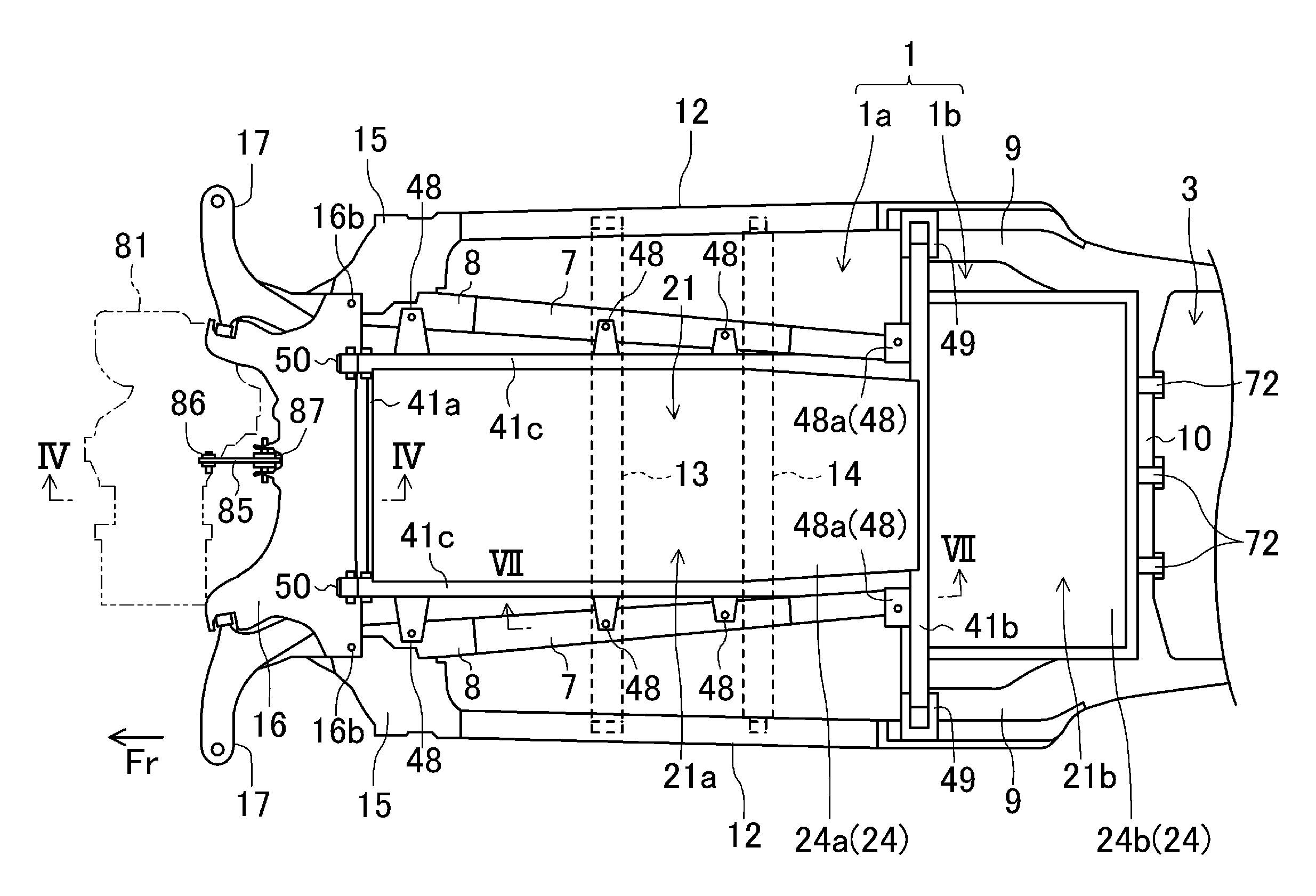
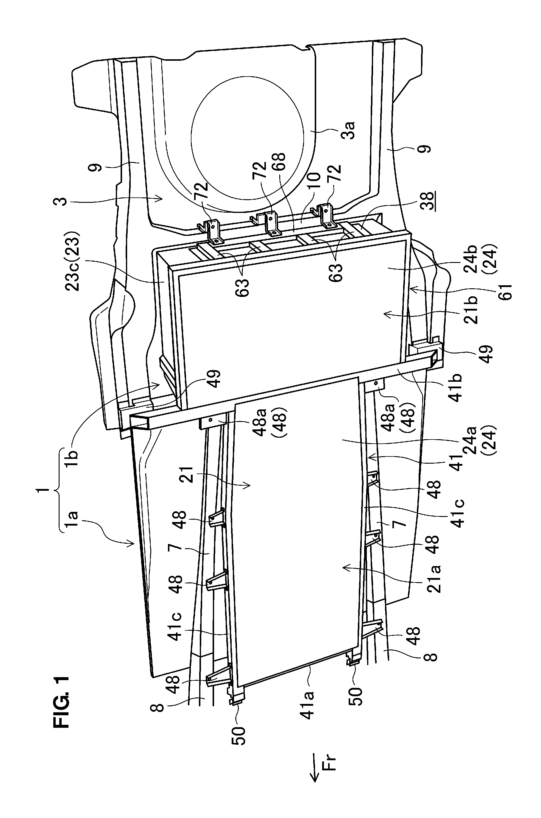
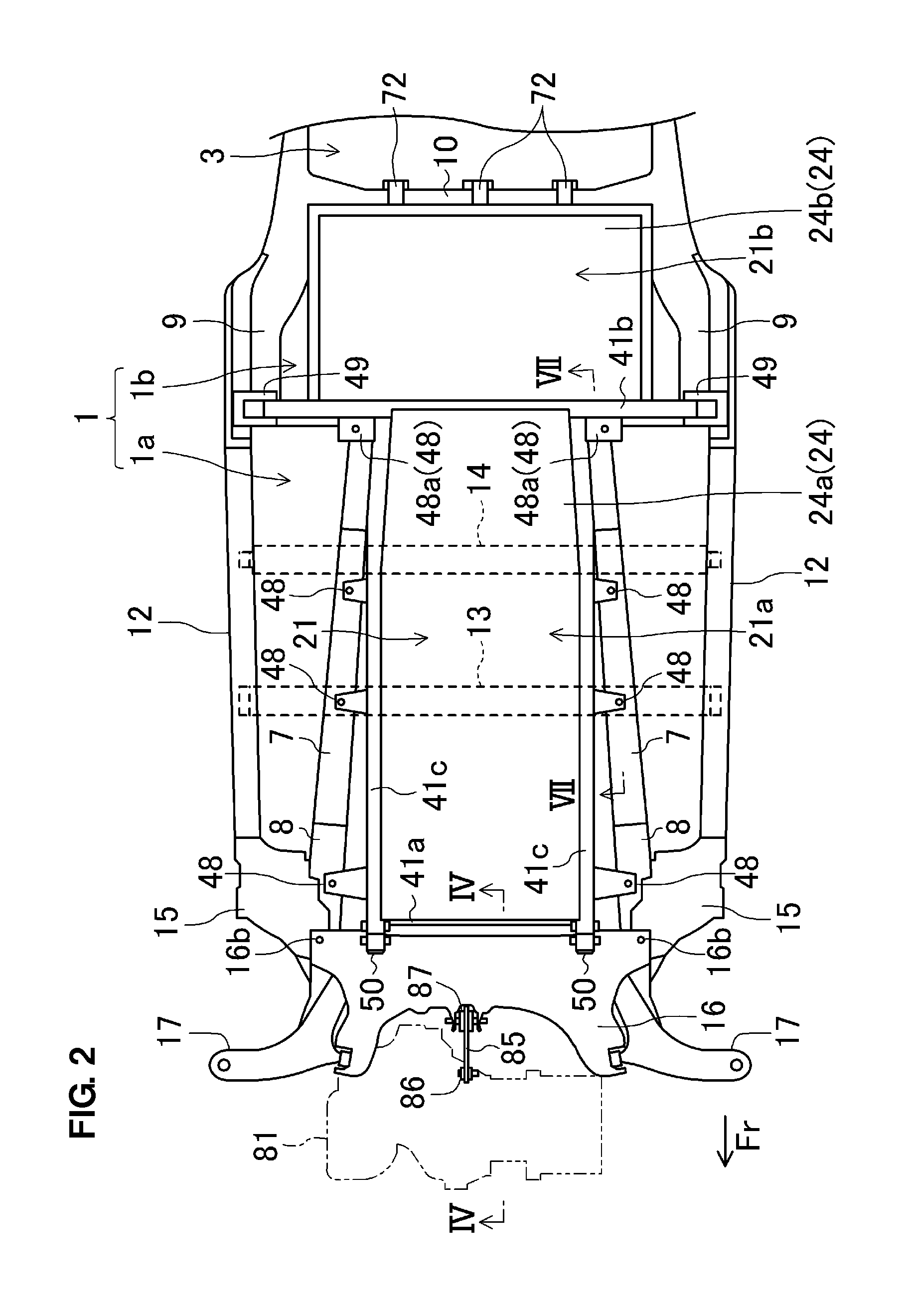
[0024]FIGS. 1 and 2 show a structure below a vehicle floor panel 1 (constituting a vehicle floor) of an electromotive vehicle (an electric vehicle in the present embodiment) which is equipped with a battery mounting structure according to the present embodiment of the present invention. Herein, the front, rear, left, right, above, or below with respect to a vehicle body will be simply referred to as the “front”“rear”“left”“right”“above” or “below.” In FIGS. 1 through 7, the vehicle front side is shown by an arrow Fr.

[0025]The vehicle floor panel 1 comprises a front floor portion 1a and a rear floor portion 1b which is located above the level of the front floor portion 1a. A step-shaped kick-up portion 1c (see FIG. 7) is formed between the front floor portion 1a and the rear floor portion 1b, and the level of the rear floor portion 1b is higher than that of the front floor portion 1a by the height of th...


PUM


Abstract

A battery unit comprises plural side connection portions which are provided at its both-side end portions in a vehicle width direction and connected to said vehicle-body member, and these connection portions are connected to a high rigidity portion of a vehicle-body member, concretely, to the vehicle-body member at a specified position where floor cross members integrally connected to a vehicle floor panel are located, to the vehicle-body member at a specified position where a torque box is located, or to the vehicle-body member at a specified position where a kick-up portion of the vehicle floor panel is located. Accordingly, the torsional rigidity of the vehicle body can be increased by utilizing the battery unit mounted below the vehicle body floor (vehicle floor panel).

Description

BACKGROUND OF THE INVENTION[0001]The present invention relates to a battery mounting structure of an electromotive vehicle in which a battery unit is mounted below a vehicle floor.[0002]In general, plural battery modules are mounted as a unit below a vehicle floor in an electromotive vehicle, such as an electric automotive vehicle. A battery unit like this is generally connected to a vehicle-body member. Japanese Patent Laid-Open Publication No. 2006-224877, for example, discloses a structure in which the frames of the unit including fuel batteries are provided along the lower walls of the extension side members extending at the vehicle-body rear side portions of the front side members, and these frames are connected to the extension side members at plural positions in the longitudinal direction by fastening bolts.[0003]Herein, in the structure of the above-described patent publication, the connection portions of the battery unit and the extension side member of the battery unit are...

Claims


Application Information

Patent Timeline
IPC IPC(8): B60R16/04
CPCB60K1/04B62D21/11B60K2001/0438
Inventor USAMI, IKUOKITA, HIROKAZUNOMURA, HIROYUKIMITOBE, NORIAKI
Owner MAZDA MOTOR CORP
Why Eureka
Try Eureka