Heating device for the tempering of preforms

Active Publication Date: 2012-04-26
KRONES AG
View PDF10 Cites 2 Cited by
  • Summary
  • Abstract
  • Description
  • Claims
  • Application Information

AI Technical Summary

Benefits of technology

[0030]Due to the segmented structure the tile can stand up to larger temperature fluctuations. It is therefore possible to minimize the distance between the infrared emitters and the back reflector. Preferably, the maximum distance between the infrared emitters and the back reflector is 50 mm. Even more preferably the maximum distance between the infrared emitters and the back reflector is 10 mm or even as low as 5 mm.
[0031]Furthermore, at least one cou

Problems solved by technology

This would lead to the production of incor

Method used


Image

  • Heating device for the tempering of preforms
  • Heating device for the tempering of preforms
  • Heating device for the tempering of preforms

Examples


Embodiment Construction

[0043]For the same or equivalent elements of the invention, identical reference numerals are used. Furthermore, for the sake of clarity, only reference numerals are represented in the various figures, which are necessary for the description of each figure. The illustrated embodiments are merely examples of how the inventive device can be designed and do not constitute final limitations.

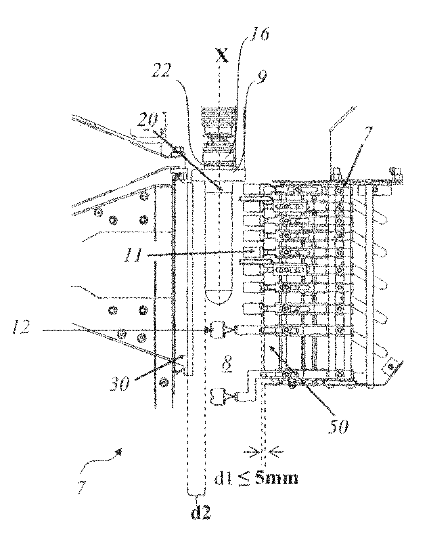
[0044]FIG. 4 shows a heating box 7 to be used in a heating device or heater according to the invention. According to the invention the back reflector 50 can be located in a very short distance d1 to the infrared emitters 11. Preferably, the distance d1 is a maximum of 5 mm. Furthermore, the distance d2 between the preform 20 and the counter reflector 30 is reduced, which also leads to a better use of the infrared radiation.

[0045]FIGS. 5a / 5b show two different views of a back reflector 15 according to the known state of the art. This consists of a single tile 90, which is for example made of ceramic ma...


PUM

PropertyMeasurementUnit
Distanceaaaaaaaaaa
Distanceaaaaaaaaaa

Abstract

A heating device for tempering preforms before processing in a stretch blow device. The heating device includes a heating alley with a plurality of infra red emitters, arranged parallel to the longitudinal axis of the tempered preforms. At least one back reflector and/or one filter is assigned to the infra red emitters, whereby the at least one back reflector and/or the at least one filter is segmented.

Description

[0001]This claims the benefit of German Patent Application DE 10 2010 049 136.5, filed Oct. 22, 2010 and hereby incorporated by reference herein.[0002]The present invention relates to a heating device for tempering preforms, especially a heating device. The invention furthermore relates to the use of a back reflector or a filter in a heating device for tempering preforms.BACKGROUND[0003]So called preforms are used for the production of plastic bottles. The preforms are made of a thermoplastic material, especially PET. The preforms are first heated and then reshaped into the desired container shape in a stretch blow device. Usually the preforms are conveyed through a heating device on a conveyor path before being processed in the stretch blow device.[0004]Each preform is already designed with an upwardly open mouth region, which usually comprises an external thread. This mouth region essentially corresponds to the mouth region of the finished bottle. The preforms are typically inject...

Claims


Application Information

Patent Timeline
IPC IPC(8): F21V7/00
CPCB29B13/024B29C49/06B29C49/6445H05B3/0057B29C2035/0822B29C49/12B29C49/6409B29C49/68B29C2949/0715B29C49/6835
Inventor SCHOENBERGER, WOLFGANGFISCHER, SIMONWUTZ, ANDREASHIRDINA, JOCHENHOLZER, CHRISTIAN
Owner KRONES AG
Why Eureka
Try Eureka