Centrifuge opening tool

a technology of centrifuges and opening tools, applied in centrifuges and other directions, can solve the problems of extremely difficult opening, and achieve the effect of increasing the mechanical advantag

Active Publication Date: 2012-04-26
G&S FAB LLC
View PDF7 Cites 11 Cited by
  • Summary
  • Abstract
  • Description
  • Claims
  • Application Information

AI Technical Summary

Benefits of technology

[0004]A centrifuge opening tool has a frame that securely holds a centrifuge drum therein. An upright tube is mounted to the frame and a brake band is rotatably secured to the upright tube. When the brake band is tightened, the centrifuge drum is securely held in place. A ring gear is secured to a lock ring. The lock ring is part of the centrifuge drum and is removable to allow access to the interior therein. A drive gear meshes with the ring gear and increases the mechanical advantage allowing a user to apply the force needed to open the lock ring even when it has been extremely compressed. A spanner wrench is placed on a drive shaft that is connected to the drive gear. Engagement pins are used to mechanically couple the gear ring and lock ring together.

Problems solved by technology

As the centrifuge spins, tremendous forces are generated which tends to compress and tighten the threads holding the centrifuge access door in place and may make opening extremely difficult.

Method used


Image

  • Centrifuge opening tool
  • Centrifuge opening tool
  • Centrifuge opening tool

Examples


Embodiment Construction

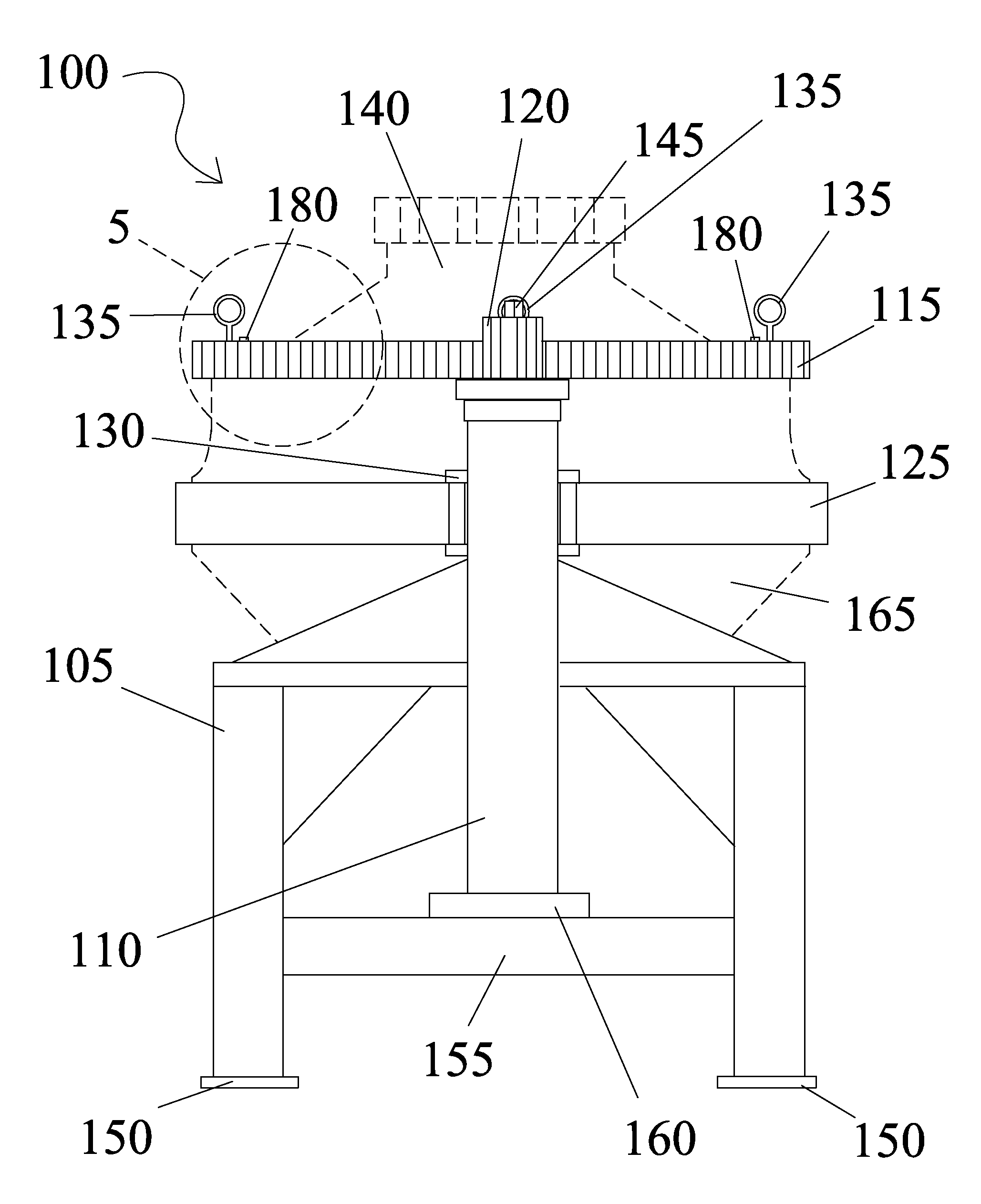
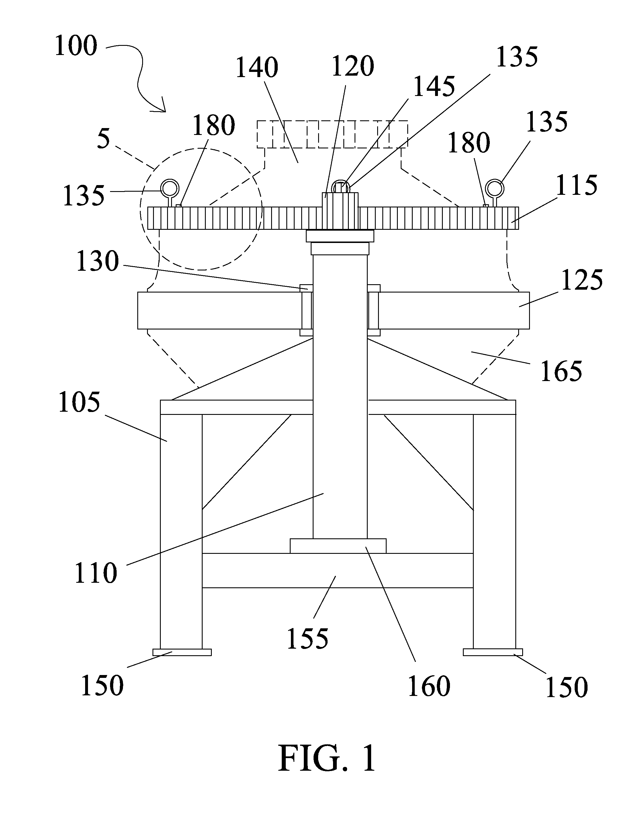
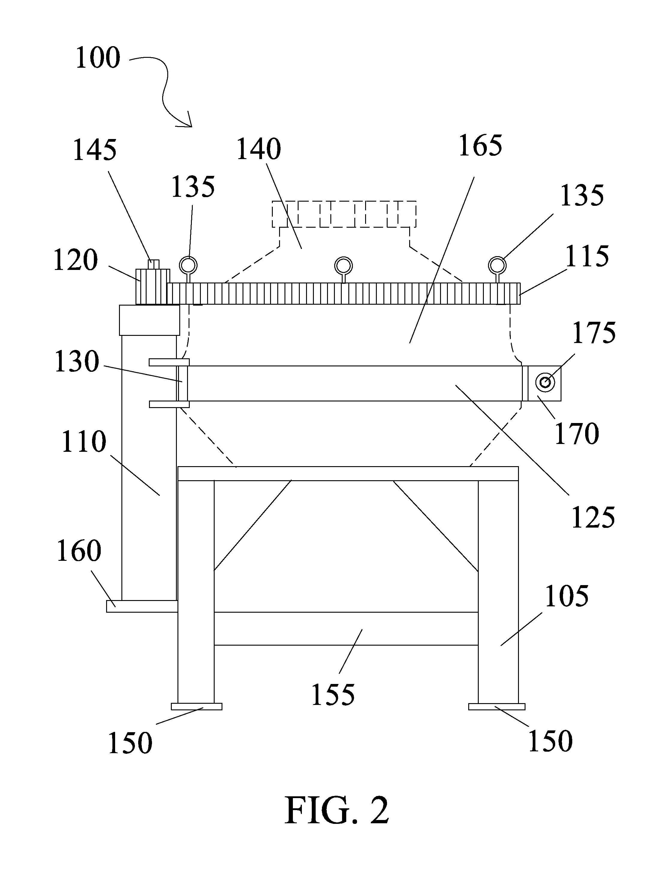
[0012]In the following detailed description of the invention, reference is made to the drawings in which reference numerals refer to like elements, and which are intended to show by way of illustration specific embodiments in which the invention may be practiced. It is understood that other embodiments may be utilized and that structural changes may be made without departing from the scope and spirit of the invention.

[0013]Referring to FIGS. 1 through 4, a centrifuge opening tool 100 is shown having a frame 105 that supports a centrifuge drum 165. A brake band 125 is made of two parts—left and right side—that is hinged using brake band holders 130 and is mounted on both sides of an upright tube 110 that is securely attached to frame 105 and secured to a tube plate 160. Frame 105 has four legs with four feet pads 150 and cross braces 155. Gussets are used to stiffen and strengthen frame 105. Brake band 125 is moved to an open position allowing centrifuge drum to be placed therein. Af...


PUM


Abstract

A centrifuge opening tool has a frame that securely holds a centrifuge drum therein. An upright tube is mounted to the frame and a brake band is rotatably secured to the upright tube. When the brake band is tightened, the centrifuge drum is securely held in place. A ring gear is secured to a lock ring. The lock ring is part of the centrifuge drum and is removable to allow access to the interior therein. A drive gear meshes with the ring gear and increases the mechanical advantage allowing a user to apply the force needed to open the lock ring even when it has been extremely compressed. A spanner wrench is placed on a drive shaft that is connected to the drive gear. Engagement pins are used to mechanically couple the gear ring and lock ring together.

Description

CROSS REFERENCE TO RELATED APPLICATIONS[0001]This application claims priority and herein incorporates by reference U.S. provisional patent application 61 / 405,430, filed Oct. 21, 2010.BACKGROUND OF THE INVENTION[0002]The development of the centrifuge as a tool to process materials is well known and fundamental to our society and the production of materials necessary for modern life. Centrifuges are used in almost every field of endeavor from isotope separation, human testing, earthquake simulation, biological and food processes, waste treatment, and oil treatment just to name a few.[0003]As the centrifuge spins, tremendous forces are generated which tends to compress and tighten the threads holding the centrifuge access door in place and may make opening extremely difficult. There is a need for a tool that allows opening of a centrifuge with relative ease.SUMMARY OF THE INVENTION[0004]A centrifuge opening tool has a frame that securely holds a centrifuge drum therein. An upright tube...

Claims


Application Information

Patent Timeline
Patent Type & Authority Applications(United States)
IPC IPC(8): B04B7/02B04B9/00
CPCB04B9/08B04B7/02B04B7/08
Inventor LAHMANN, THOMAS
Owner G&S FAB LLC
Why Eureka
Try Eureka