Coupling structure between screw head and tightening tool

a technology of screw head and screw head, which is applied in the direction of wrenches, screwdrivers, fastening means, etc., can solve the problems of screw head and/or tool end deterioration, significantly complicating the manufacturing, both of the screw and the tool, and achieving high tightening torque, the effect of reducing the risk of deterioration of said components

Active Publication Date: 2012-05-03
UNIVERSAL BALL HEAD
View PDF6 Cites 12 Cited by
  • Summary
  • Abstract
  • Description
  • Claims
  • Application Information

AI Technical Summary

Benefits of technology

[0007]Another object of the invention is to attain a coupling structure between screw head and tightening tool which enables to transmit a high tightening torque on the screw, both for the threading and unthreading thereof, without any risk of causing deterioration of said components.
[0013]On the other hand, the curved concave shape of the recess of the screw head and the curved convex shape of the protuberance of the tool end secure the coupling between both components although the axis thereof is not perfectly aligned, even with deviations of up to 30°, which facilitates action on the screw head even when there is difficult accessibility of said head.

Problems solved by technology

In all cases in which the tool does not affect the screw head in alignment with the axis of said screw, a correct action on the screw is not possible, both for the threading and unthreading thereof, making it impossible to carry out these operations or at least requiring great efforts which also cause the deterioration of the screw head and / or the tool end.
This configuration considerably complicates the manufacturing, both of the screw and of the tool and it also has the risk of breaking the screw head when it is subjected to high tightening torques.

Method used


Image

  • Coupling structure between screw head and tightening tool
  • Coupling structure between screw head and tightening tool
  • Coupling structure between screw head and tightening tool

Examples


Embodiment Construction

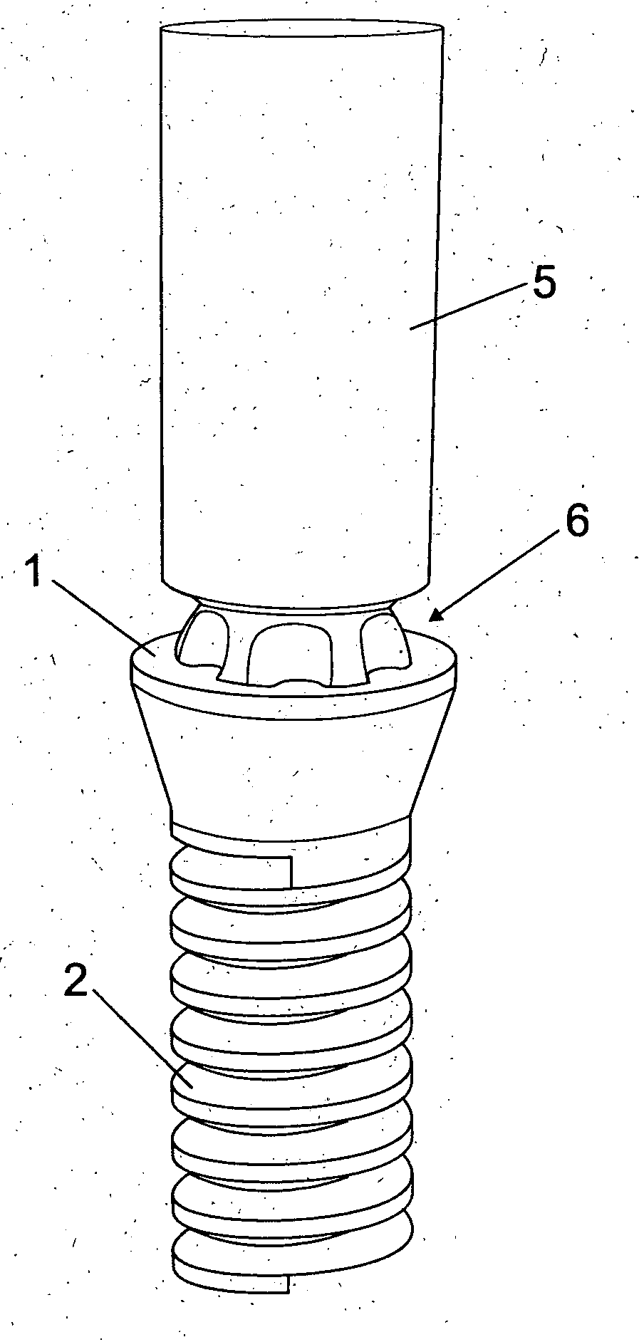
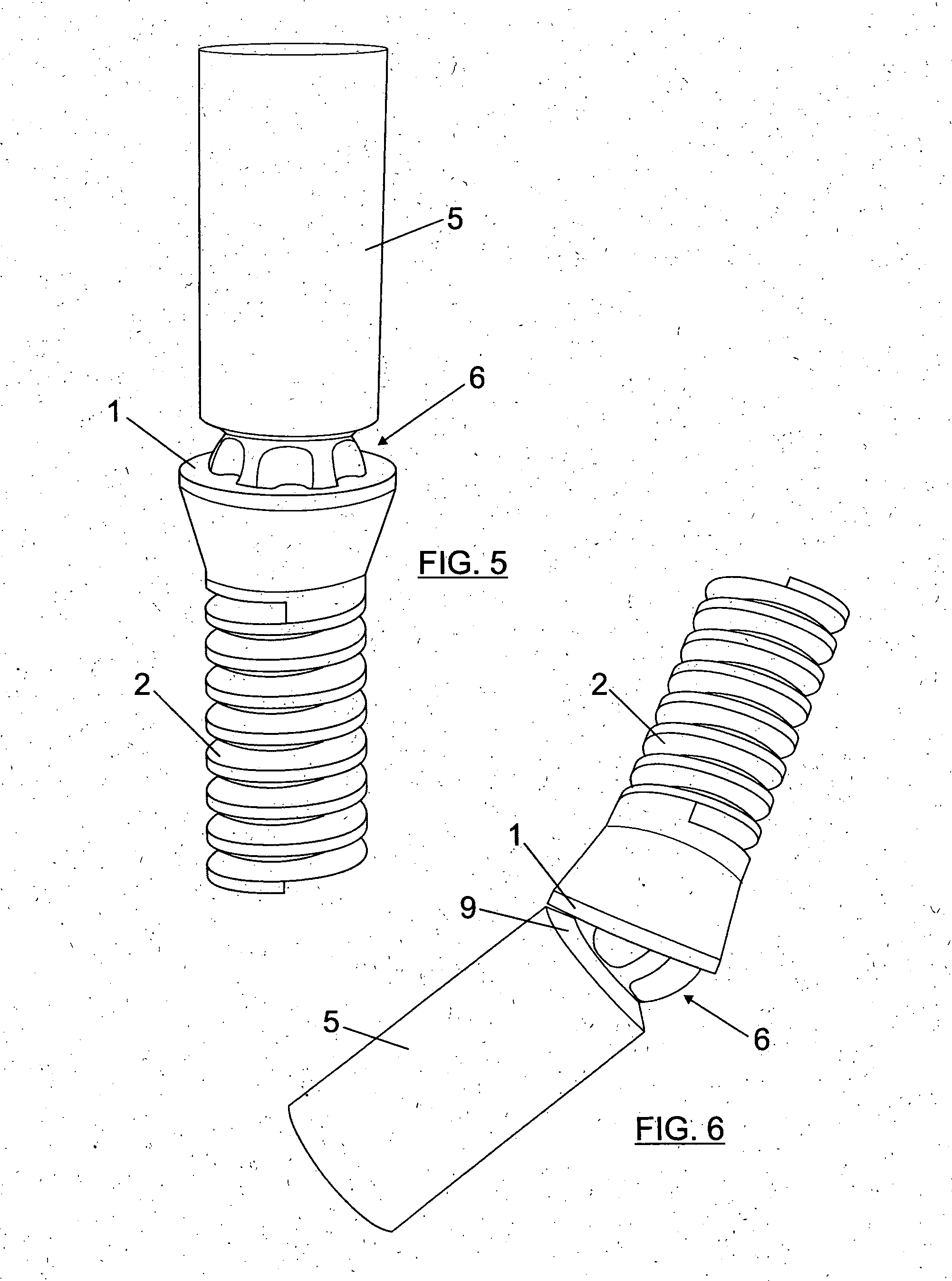
[0006]The object of the present invention is a coupling structure between screw head and tightening tool, allowing actions on the screw head, both in threading and unthreading operations, even when the tool is not aligned with the axis of said head, being possible to form with it angles of up to 30°.

[0007]Another object of the invention is to attain a coupling structure between screw head and tightening tool which enables to transmit a high tightening torque on the screw, both for the threading and unthreading thereof, without any risk of causing deterioration of said components.

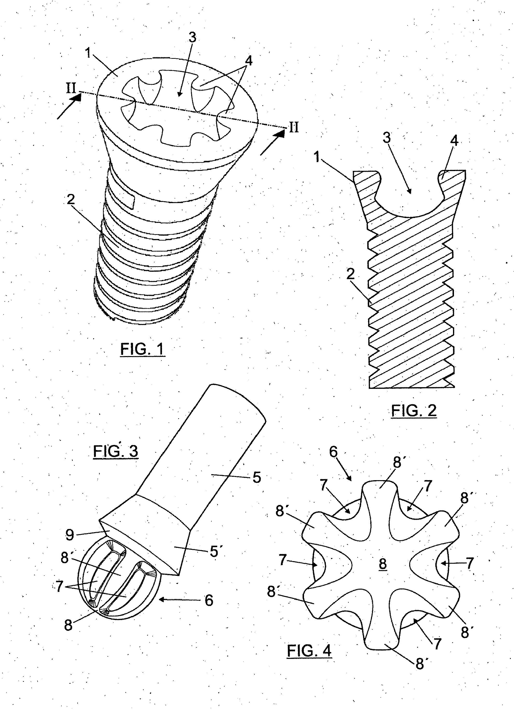
[0008]According to the present invention, the coupling structure between screw head and tightening tool comprises a recess with a curved concave surface on the free base of the screw head, and a protuberance with a curved convex surface finishing the end of the tightening tool and which has a diameter slightly smaller than that of the recess of the screw head.

[0009]The curved concave recess of the screw head...


PUM


Abstract

A coupling structure between a screw head and a tightening tool includes a recess (3) with a curved concave surface on the free base of the head (1) of the screw (2) and a protuberance (6) with a curved convex surface finishing the end of the tool (5). The recess has axial projections (4) internally and the protuberance (6) has meridional grooves (7).

Description

FIELD OF THE INVENTION[0001]The present invention refers to a coupling structure between screw head and tightening tool, designed to secure a perfect coupling between the tool and the screw head, even when the axes of both components are not completely aligned, allowing inclinations of the tool, with respect to the axis of the screw head, of up to 30°.BACKGROUND OF THE INVENTION[0002]Traditional coupling structures between screw head and tightening tool are constituted by a diametric groove done in the screw head and a tool end ending in a wedge, with a profile which can be inserted in the groove of the screw head.[0003]There are also known coupling structures called star couplings, in which the head has a cross-shaped recess and the tool end finishes in a cross-shaped point.[0004]In all these cases, in order to attain a threading or unthreading of the screw, the axis of the tool must be aligned with the screw head, which requires good accessibility of the screw. In all cases in whi...

Claims


Application Information

Patent Timeline
Patent Type & Authority Applications(United States)
IPC IPC(8): B25B15/00F16B23/00
CPCB25B13/481F16B23/003B25B15/005
Inventor FARRE BERGA, ORIOLFARRE BERGA, RAMON
Owner UNIVERSAL BALL HEAD
Why Eureka
Try Eureka