
Electrical Supply Apparatus

a technology of electrical supply and power supply, which is applied in the direction of coupling device connection, transmission system, sustainable building, etc., can solve the problems of a substantial power draw when all devices are in standby mode, and the task may take a substantial length of tim

Inactive Publication Date: 2012-05-03
JACKSON STEWART JOHN ROBERT
View PDF51 Cites 240 Cited by
  • Summary
  • Abstract
  • Description
  • Claims
  • Application Information

AI Technical Summary

Benefits of technology

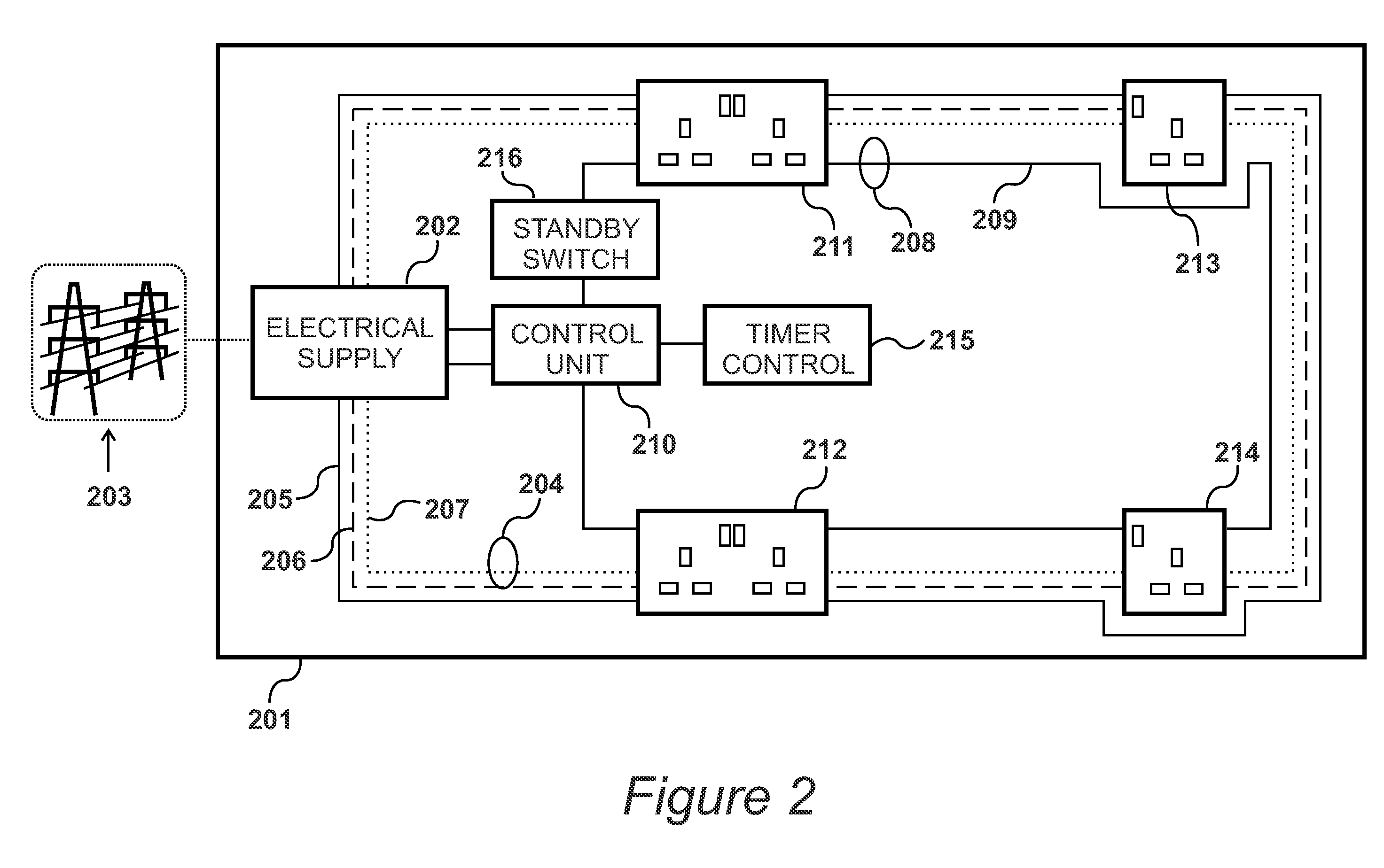
[0008]According to a second aspect of the present invention, there is provided a method of installing an electrical supply to a building, comprising the steps of installing a first type of socket and a second type of socket, installing an electrical supply unit for providing electrical power, installing a first mains circuit for conveying electrical power to said first type of socket, installing a second mains circuit for conveying electrical power to said second type of socket, and installing a control unit configured to interrupt the supply of electrical power through said second mains circuit, and thus to said second type of socket, wherein the electrical supply is configured such that the interruption of electrical power to said second mains circuit does not affect the supply of electrical power to said first type of socket.

Problems solved by technology

Whilst the device may use substantially less power than it would when in operation, there is still a power draw associated with the standby state.
Given many buildings contain a large number of such electronic devices, the power draw when all of the devices are in standby mode is quite significant.
A problem is encountered when a user wishes to minimise the power draw of electronic devices when a standby mode is not required.
A user may unplug devices from their associated sockets, but this task may take a substantial length of time, especially in office environments.

Method used


Image

  • Electrical Supply Apparatus
  • Electrical Supply Apparatus
  • Electrical Supply Apparatus

Examples


Embodiment Construction

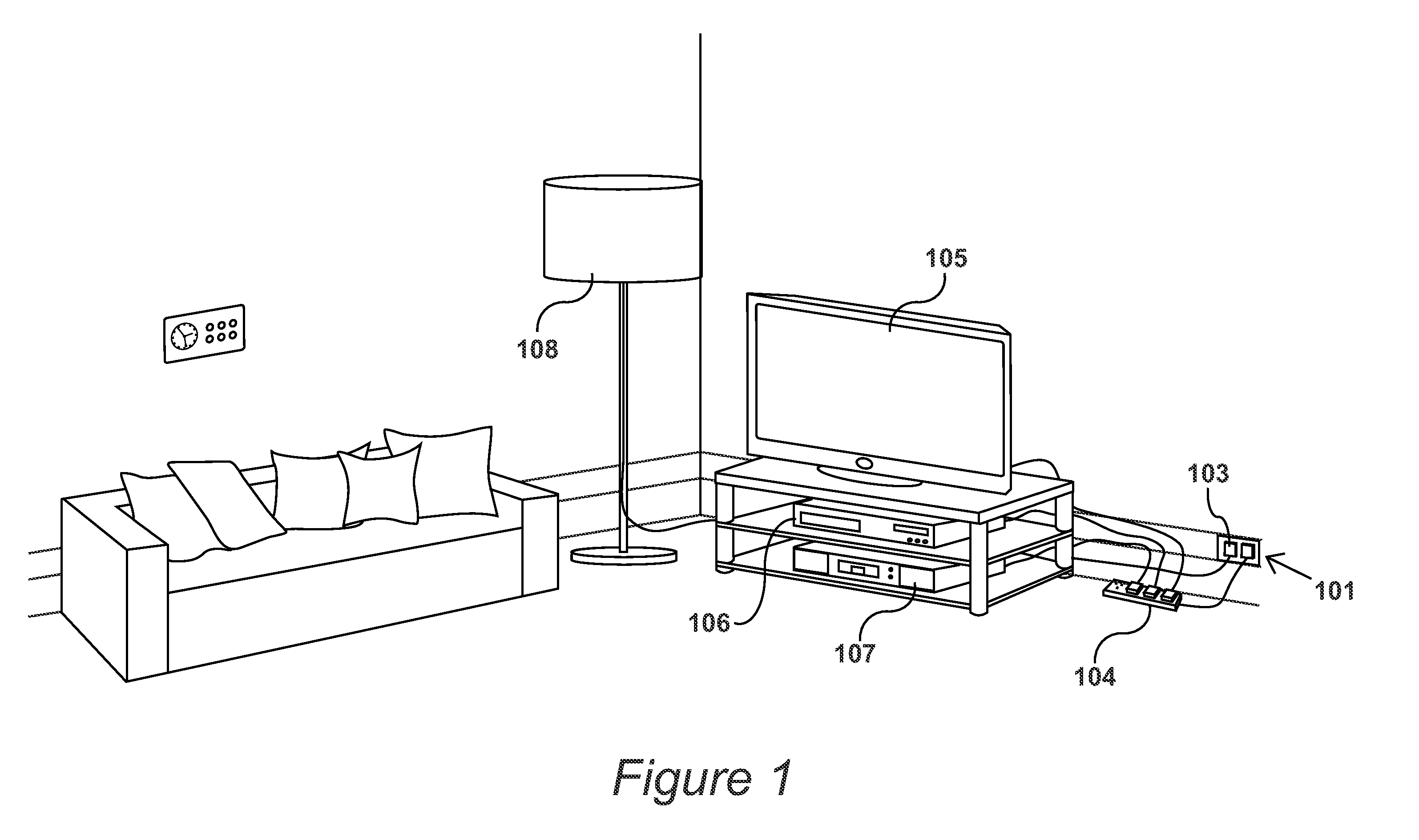
[0021]FIG. 1

[0022]An environment in which the present invention may be used is shown in FIG. 1. In this case, the environment is as living room in a household. The living room includes an outlet 101 comprising a first socket 102, and a second socket 103. Connected to first socket 102 is an extension cord 104, connected to which is a television 105, a DVD player 106 and a set top box 107. When in standby mode, devices such as television 105, DVD player 106 and set top box 107 consume around 5 to 10 Watts each. Thus if left in standby mode overnight, an electrical power draw of around 100 Watt-hours will be recorded by these devices alone.

[0023]Connected to second socket 103 is a lamp 108. Lamp 108 does not have a standby mode, and its switch completely interrupts its electrical supply. Additionally, the lamp may wish to be used by a house owner during the night in order to navigate through the living room. This is in contrast to devices such as television 105, DVD player 106 and set ...


PUM

PropertyMeasurementUnit
Poweraaaaaaaaaa
Flow rateaaaaaaaaaa

Abstract

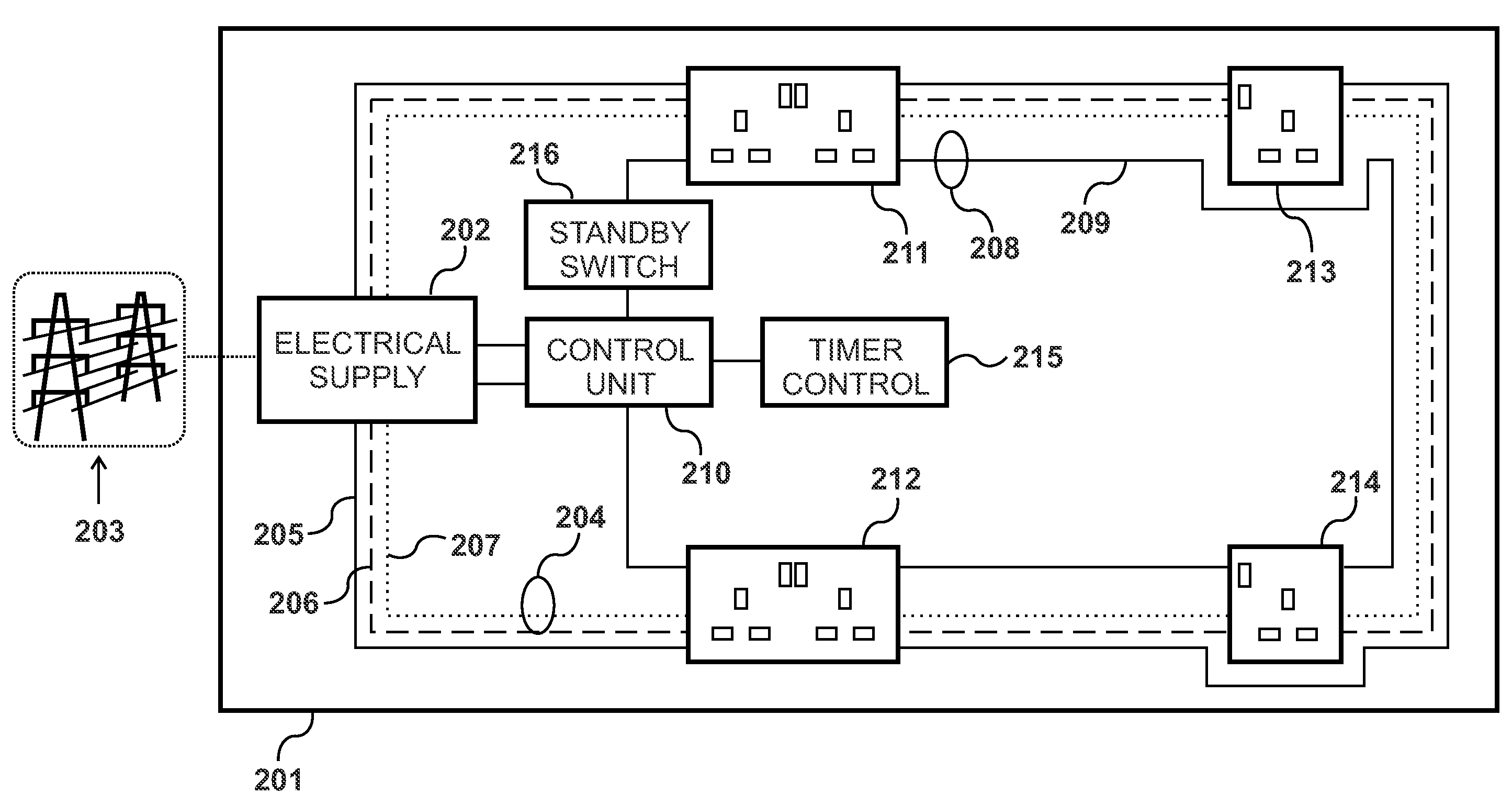
Electrical supply apparatus (201) for providing electrical power to a first type of socket and a second type of socket (410). The apparatus comprises an electrical power source (420) for providing electrical power, a first mains circuit (204) for conveying electrical power to the first type of socket, a second mains circuit (208) for conveying electrical power to the second type of socket, and a control unit (210) configured to interrupt the supply of electrical power through the second mains circuit, and thus to the second type of socket. The interruption of electrical power through the second mains circuit does not interrupt the supply of electrical power to the first type of socket.

Description

CROSS REFERENCE TO RELATED APPLICATIONS[0001]This application claims priority from United Kingdom Patent Application No. 10 02 654.0, filed 17 Feb. 2010, United Kingdom Patent Application No. 10 02 655.7, filed 17 Feb. 2010, and United Kingdom Patent Application No. 10 05 848.5, filed 8 Apr. 2010, which are hereby incorporated by reference in their entireties.BACKGROUND OF THE INVENTION[0002]1. Field of the Invention[0003]The present invention relates to controlling the supply of electrical power to electronic devices through a mains supply.[0004]2. Description of the Related Art[0005]Many electronic devices include a standby feature whereby the device enters an off state, but is still able to be turned back on through the use of a remote control, for example. Whilst the device may use substantially less power than it would when in operation, there is still a power draw associated with the standby state. Given many buildings contain a large number of such electronic devices, the pow...

Claims


Application Information

Patent Timeline
IPC IPC(8): H02J3/00H01R43/00
CPCH01R13/652H01R13/665H01R13/70H01R24/78H01R25/006H02G3/16Y10T307/406Y10T29/49117Y04S20/00Y02B90/20H02J3/005H02J13/0006H02G3/18G04G15/00H01H43/00
Inventor JACKSON, STEWART JOHN ROBERT
Owner JACKSON STEWART JOHN ROBERT
Learn More