Sight system

a technology of sight system and rifle, applied in the field of sight system, can solve the problems of user loss of situational awareness, user may be unaware of other events, user may lose situational awareness, etc., and achieve the effect of effectively sighting the rifle, without compromising situational awareness

Active Publication Date: 2012-05-03
SUREFIRE LLC
View PDF11 Cites 105 Cited by
  • Summary
  • Abstract
  • Description
  • Claims
  • Application Information

AI Technical Summary

Benefits of technology

[0008]In accordance with various embodiments described herein, a sight system (e.g., also referred to as an aiming system) is provided which may be selectively used in a variety of different ways. For example, the sight system may be positioned on a rifle to provide a rifle sight system. In one embodiment, the sight system may be positioned on and substantially parallel to a rifle barrel. While positioned in this manner, the sight system may be located a substantial distance away from a user's eye. Advantageously, such an implementation may permit a user to effectively sight the rifle without blocking the user's peripheral vision and without compromising situational awareness.
[0010]In one embodiment, a sight system may provide zoomed images on a display using, for example, optical zoom and / or digital zoom features (e.g., telescopic zoom features) of a camera and / or a processing block. As a result, images of a target scene may be magnified as desired by a user. By combining such zoom capabilities with reflex sight features, a single sight system may be used in place of separate red dot sight and zoom sight devices. As a result, the number of devices operated by the user may be reduced.
[0019]Advantageously, various embodiments further described herein may provide flexibility in the use and operation of sight systems. For example, users familiar with reflex sights or occluded sights may configure the sight system to emulate the operation of reflex or occluded sights as may be desired in particular applications.

Problems solved by technology

Each of these devices has its own advantages and disadvantages with respect to simplicity, ruggedness, size, weight, cost, accuracy, usability in different ambient light level, speed of use, maintenance of situational awareness, and efficacy in developing both reactive and precision shooting skills through both live fire and dry fire practice.
One particular problem associated with conventional sighting devices is the loss of situational awareness experienced by users.
Unfortunately, this narrow field of view may cause the user to lose situational awareness.
Specifically, the user may be unaware of other events occurring outside a target area.
Thus, the user may be placed at high risk when using sighting devices which limit the user to only a narrow field of view.
Another problem associated with conventional sighting devices is a lack of flexibility.
However, many existing sighting devices permit the user to use only a single sighting method.
Moreover, if a user desires to change the method of sighting (e.g., to use different types of sights in different conditions), it may be cumbersome and impractical for the user to replace one type of sighting device for another type, especially in stressful or combat situations.
As a result, users are often forced to adapt their skills to use a particular available type of sighting device, rather than the sighting device adapting to the user.

Method used


Image

  • Sight system
  • Sight system
  • Sight system

Examples


Embodiment Construction

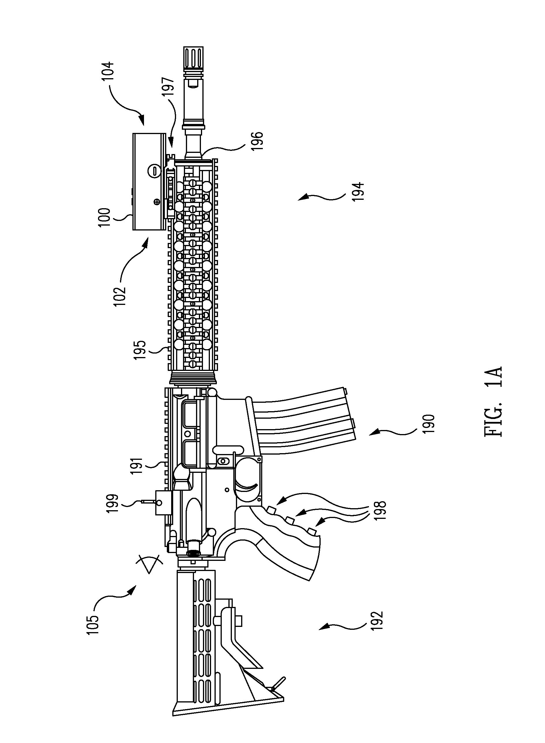
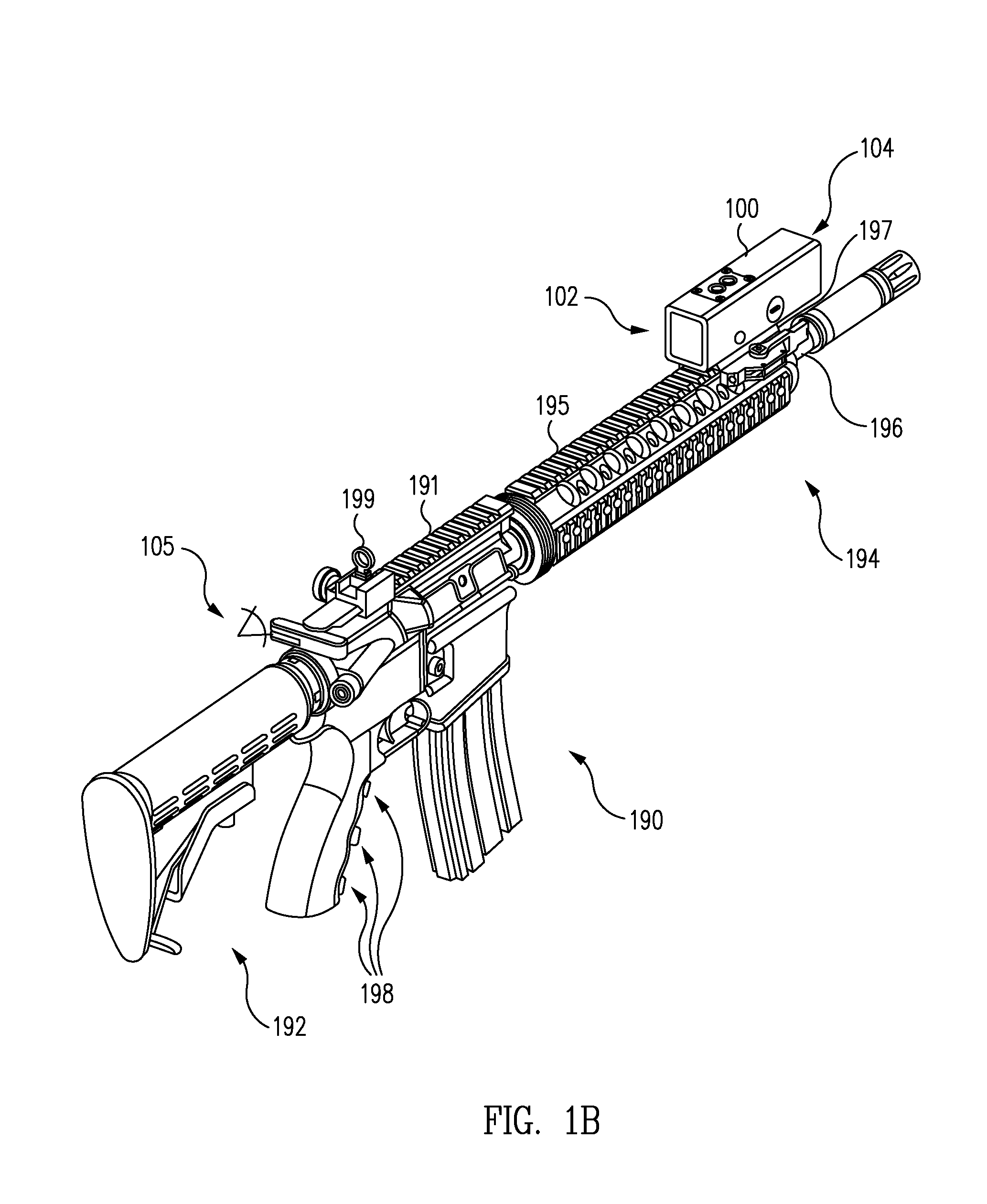
[0045]FIGS. 1A-C illustrate several views of a sight system 100 including an integrated camera mounted on a rifle 190 in accordance with various embodiments of the disclosure. When mounted on rifle 190, sight system 100 may be used as a rifle sight system. For example, in one embodiment, rifle 190 may be an M4 assault rifle as shown in FIGS. 1A-C.

[0046]In one embodiment, sight system 100 may be mounted on a rail 195, such as a Picatinny rail, using a rail clamp mount 197. In one embodiment, rail clamp mount 197 may be implemented as a rail clamp mount set forth in U.S. Pat. No. 7,712,242 entitled “RAIL CLAMP MOUNT” which is incorporated herein by reference in its entirety. Although sight system 100 is illustrated in FIGS. 1A-C as being mounted on top of rifle 190, other mounting configurations are also contemplated. For example, in another embodiment, sight system 100 may be mounted on a left or right side of rifle 190 using appropriate mount and / or rail structures (e.g., standard m...


PUM


Abstract

A sight system is provided which may be selectively used in a variety of different ways. In one example, the sight system may be positioned on a rifle to provide a rifle sight system. In this example, the sight system may be positioned on the rifle barrel a substantial distance away from a user's eye. Advantageously, such an implementation may permit a user to effectively sight the rifle without compromising situational awareness. In another example, the sight system may be used to provide a telescopic sight with a reticle (e.g., a dot, crosshair, mark, or other appropriate shape) superimposed on an image (e.g., a zoomed or non-zoomed image) displayed from a camera. In another example, the sight system may be used to provide an occluded sight in which a camera and / or display of the sight system is disabled. As a result, a reticle may be displayed over an opaque background.

Description

CROSS-REFERENCE TO RELATED APPLICATIONS[0001]This patent application is a continuation-in-part of U.S. patent application Ser. No. 12 / 914,597 filed Oct. 28, 2010, which is incorporated herein by reference in its entirety.BACKGROUND[0002]1. Technical Field[0003]The present disclosure generally relates to sighting devices and more particularly to sight systems that generate a beam of light that enters a user's eye to produce a luminous reticle such as a dot or mark that is utilized for aiming small arms or other devices.[0004]2. Related Art[0005]Various types of sighting devices have been developed to enable the user of small arms such as handguns, rifles, shotguns, and submachine guns to aim these weapons. Each of these devices has its own advantages and disadvantages with respect to simplicity, ruggedness, size, weight, cost, accuracy, usability in different ambient light level, speed of use, maintenance of situational awareness, and efficacy in developing both reactive and precisio...

Claims


Application Information

Patent Timeline
Patent Type & Authority Applications(United States)
IPC IPC(8): G02C11/04G02B23/00G01C3/02F41G1/38F41G1/387
CPCF41G1/30F41G1/38G02B7/004G02B23/10
Inventor MATTHEWS, JOHN W.MCCRICKERD, JOHNBUCZEK, MARKSQUIRE, MARK
Owner SUREFIRE LLC
Why Eureka
Try Eureka