Total disc replacement device

a total disc and disc technology, applied in the field of total disc replacement devices, can solve the problems of limited motion of the shell relative to one another, complex natural motion pattern of two adjoining vertebral bodies, and inability to allow rigid limitation of the lateral motion of the shell

Active Publication Date: 2012-05-03
DEPUY SYNTHES PROD INC
View PDF20 Cites 4 Cited by
  • Summary
  • Abstract
  • Description
  • Claims
  • Application Information

AI Technical Summary

Benefits of technology

[0017]In a preferred embodiment said spacer extends into the gap between the first and second constraint means, thus allowing the advantage of a damping effect in case of relative motion of the first and second apposition members.
[0050]possible osteophytes on the posterior periphery of the vertebral endplates which the surgeon decides not to remove are taken into consideration, i.e. the intervertebral prosthesis can be positioned easier because the prosthesis can be manipulated around the undulations.

Problems solved by technology

However, the natural motion pattern of two adjoining vertebral bodies is very complex due to the surrounding structures which provide mechanical stabilization.
Furthermore, the surfaces of the shells which are facing each other are provided with constraint means by means of which the motion of the shells relative to one another is limited.
Nevertheless, the disclosed configuration of the constraint means does not allow a rigid limitation of the lateral motion of the shells relative to one another until the implant is completely compressed.
The pin being laterally displaceably arranged in the bore together with the lateral wall of the bore serve as constraint means but since the second constraint means are configured at the elastic core said constraint means do not allow to rigidly limit the lateral motion and the pivoting of the two apposition members relative to one another within a desired range.
Disadvantageously, the inner constraint means are arranged at the resilient central body and do therefore not allow a rigid limitation of the range of motion.

Method used


Image

  • Total disc replacement device
  • Total disc replacement device
  • Total disc replacement device

Examples


Embodiment Construction

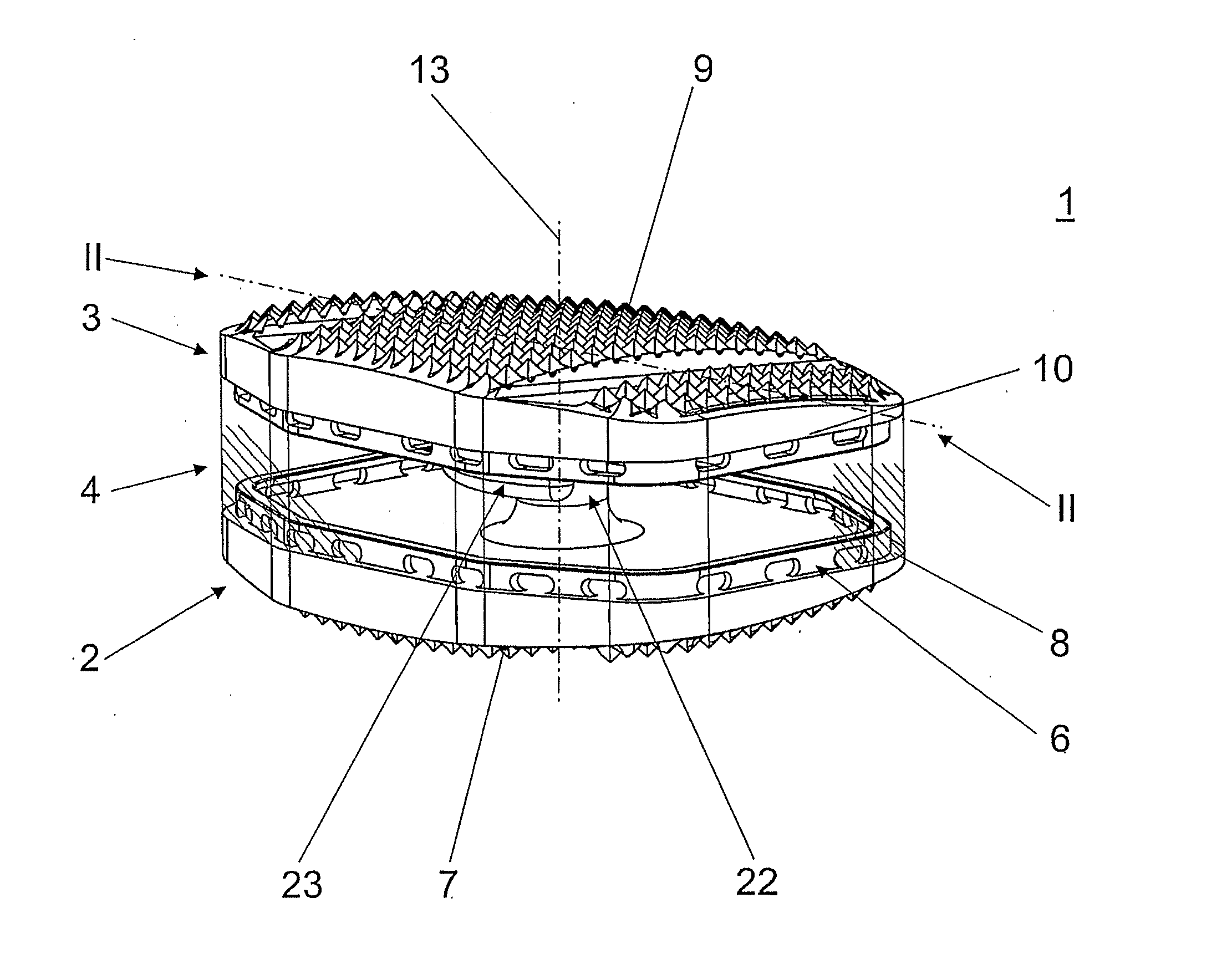
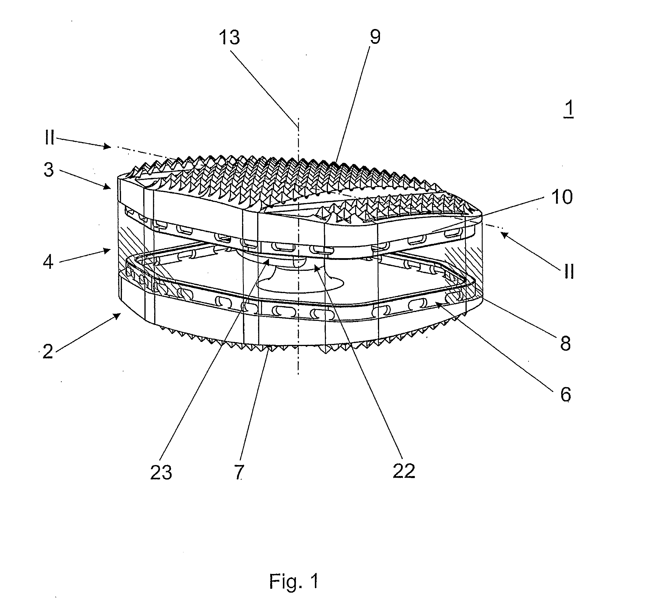
[0077]In FIG. 1 an embodiment of a total disc replacement device 1 according to the invention is represented which comprises a first and a second plate-shaped apposition member 2,3 and an elastic spacer 4 disposed between the first and second apposition member 2,3. The first and second apposition members 2,3 and the elastic spacer 4 are being cut by a central axis 13 extending along the longitudinal axis of the vertebra. The first and second apposition members 2,3 each comprise an apposition surface 7,9 and an intermediate 8,10 whereby said apposition surfaces 7,9 are apt to abut the end plates of the adjoining vertebral bodies and whereby said intermediate surfaces 8,10 are arranged facing each other. Furthermore, the elastic spacer 4 comprises a first and a second surface which are essentially parallel and abut an intermediate surface 8,10 of the apposition members 2,3 each. In order to limit the mutual translation of the apposition members 2,3 transverse to the central axis 13 th...


PUM


Abstract

An intervertebral implant for implantation between an upper vertebra and a lower vertebra having a central axis. The implant may have a first member with a top surface for contacting at least a portion of the upper vertebra and a bottom surface as well as a second member with a top surface and a bottom surface for contacting at least a portion of the lower vertebra. An elastic spacer may be disposed between the first member and the second member. Contraints may be employed to to limit the amount of lateral movement between the first and second members.

Description

CROSS REFERENCE TO RELATED APPLICATIONS[0001]This application is a continuation of U.S. patent application Ser. No. 11 / 719,355, filed May 15, 2007, which is incorporated by reference as if fully set forth.FIELD OF INVENTION[0002]The invention relates to a total disc replacement device to be used as a replacement of an intervertebral disc.DESCRIPTION OF THE PRIOR ART[0003]Currently, degenerated intervertebral discs are treated with fusion cages for arthrodesis and lower grade degenerated discs are replaced by arthroplasty devices. These devices contain mechanical elements including an articulating portion, e.g. a ball-and-socket joint. Such devices shall mimic the segmental motion pattern. However, the natural motion pattern of two adjoining vertebral bodies is very complex due to the surrounding structures which provide mechanical stabilization. Facet joints, remaining ligaments or residual fragments of the annulus fibrosis are part of the segmental stabilization.[0004]For the curre...

Claims


Application Information

Patent Timeline
Patent Type & Authority Applications(United States)
IPC IPC(8): A61F2/44
CPCA61F2/442A61F2/4425A61F2002/30112A61F2002/30383A61F2002/30448A61F2002/30476A61F2002/30563A61F2002/30574A61F2002/30841A61F2002/30971A61F2002/448A61F2220/0025A61F2220/005A61F2230/0004
Inventor LECHMANN, BEATFEIGENWINTER, GREGORBUERKI, ROGER
Owner DEPUY SYNTHES PROD INC
Why Eureka
Try Eureka