Resilient Shoe With Pivoting Sole

Inactive Publication Date: 2012-05-10
ELNEKAVEH ALEXANDER
View PDF11 Cites 28 Cited by
  • Summary
  • Abstract
  • Description
  • Claims
  • Application Information

AI Technical Summary

Benefits of technology

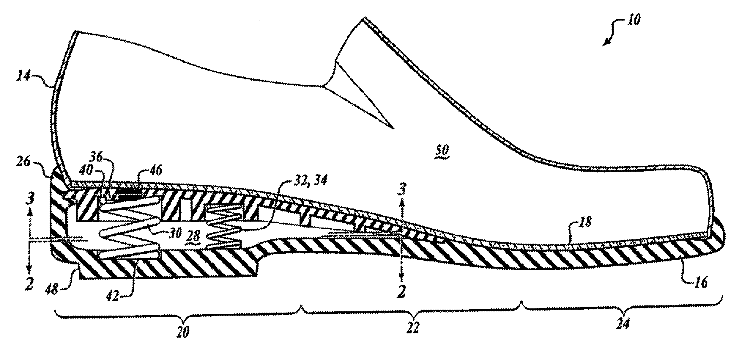
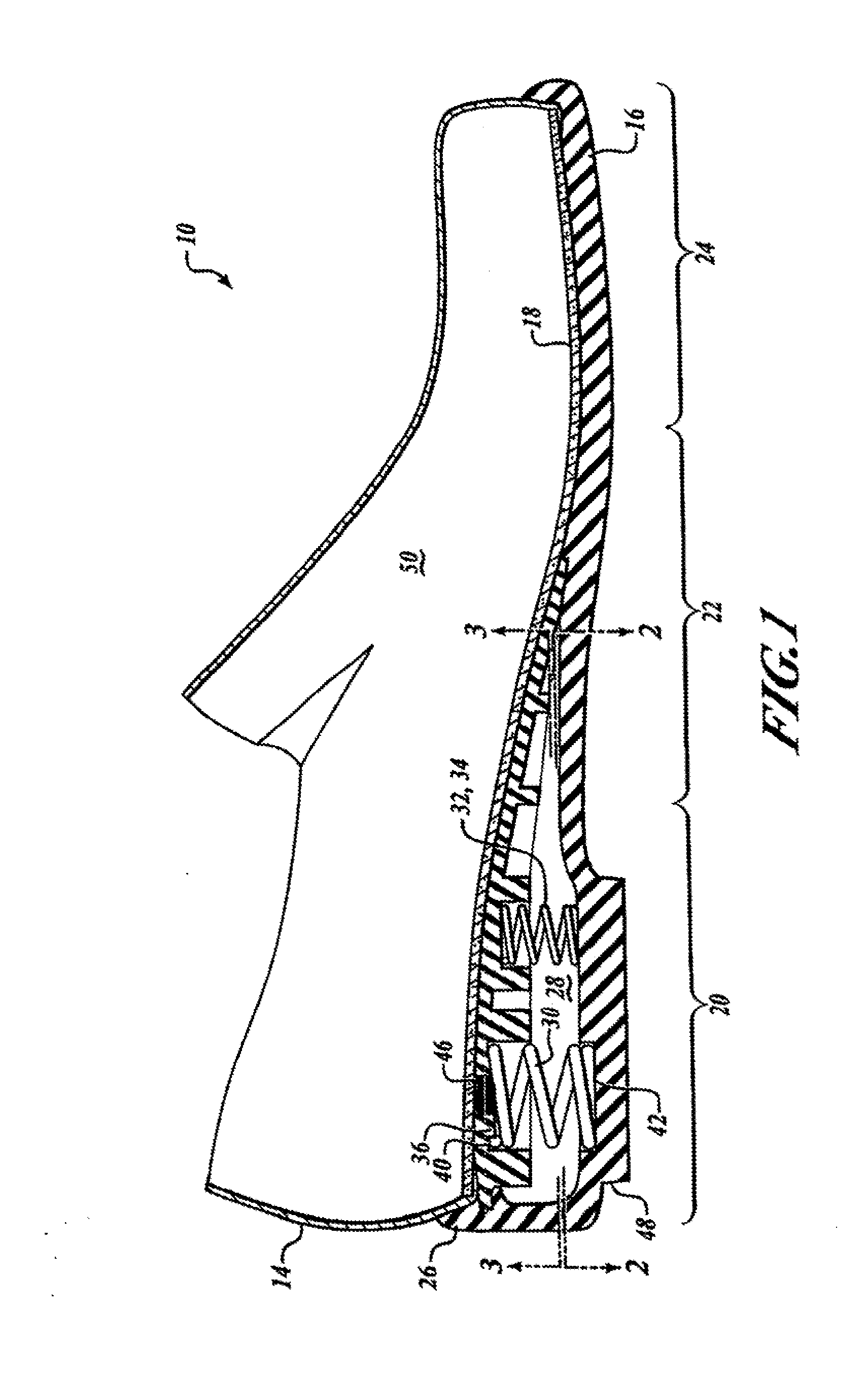
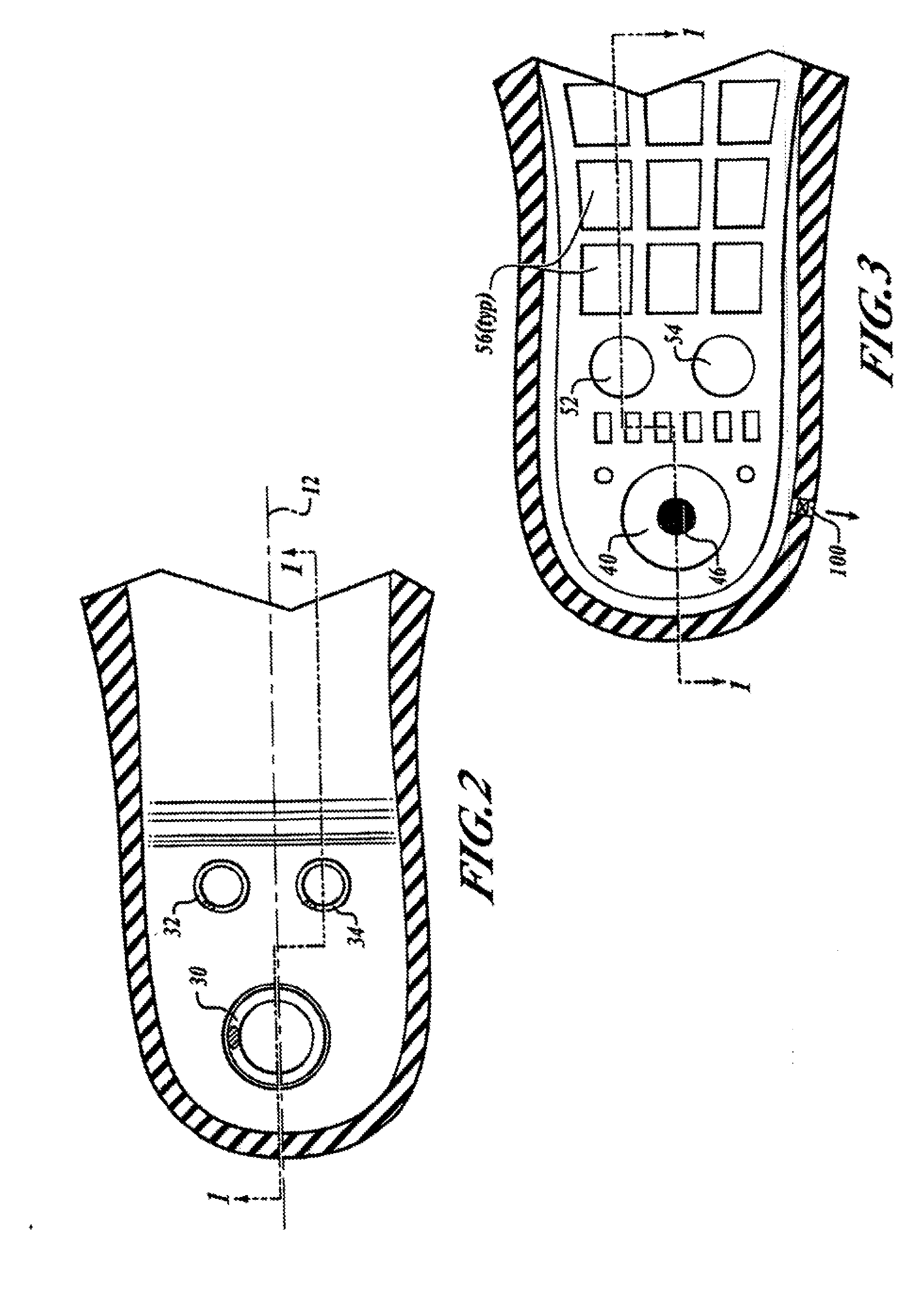
[0013]One embodiment of the invention includes a blended heel made from a resilient material and has a cavity extending under the entire instep portion of the shoe's upper. Compression springs are placed in the cavity, including a mainspring located at approximately the heelstrike point and two auxiliary springs for stability located forward of the mainspring toward the shoe's toe. The extended cavity provides even resiliency throughout the upper sole without having to resort to metal plates. The springs assist the resilient walls of the cavity, which extends under the instep portion of the shoe, in supporting the wearer's foot, and the spring's compression load is distributed throughout the sole by a resilient layer of softer rubber adjacent the sole.
[0014]The blended heel of the invention extends under the sole in a wedge-type configuration. This extension provides arch support and resiliency at the shoe's instep, or midsole. In one or more embodiments, the heel includes a height enhancer to provide lift without the appearance of “elevator shoes.” This pad located under the heel portion also serves to distribute the load of the springs a

Problems solved by technology

Conventional shoes are often uncomfortable due to a lack of resiliency in the sole, particularly in the heel area.
Inflexible heels do not promote walking or standing for long periods of time because they lack substantial cushioning and resiliency to accommodate pressure exerted on a wearer's feet.
This lack of cushioning causes undue pressure and force-of-impact to be felt up into the knees, spine, and various other joints.
Compressible heels having recessed chambers and springs in some cases are not new.
Conventional shoes also fail to provide a flow of fresh air through the inside of the sole around an individual's feet.
Lewis' shoe, however, uses metal plates (circular metal disks) above and below the coil spring(s) to help distribute pressure and also has no real cavity or resiliency in the sole.
U.S. Pat. No. 2,257,482 to Resko (1941) discloses using lugs to better seat the coil spring in the defined heel, but still uses a metal reinforcing plate between the upper and lower soles to distribute pressure, also lacking resiliency in the heel.
Further, there is a metal plate above the springs in the heelstrike area, so the wearer's foot still strikes against a hard surface.
Lombardino U.S. Pat. No. 5

Method used


Image

  • Resilient Shoe With Pivoting Sole
  • Resilient Shoe With Pivoting Sole
  • Resilient Shoe With Pivoting Sole

Examples


Example

[0059]FIG. 9 illustrates a second embodiment sport shoe 200 with an upper portion 202 and sole 204, wherein the sole 204 comprises an outsole 206, and a midsole 208. Referring to FIG. 10, the outsole 206 is attached to the midsole 208, together forming a heel 209. The midsole 208 includes a first part 210 and a second part 212. The first part 210 of the midsole 208 is designed to reside substantially under the heel of a wearer, while the second part 212 supports the remainder of the wearer's foot.

[0060]Referring to FIG. 11A, a cross section of the sports shoe 200, outsole 206, midsole 208 and related structures are shown in an uncompressed state. Here, the first part 210 of the midsole 208 is disposed above and engaged by a series of springs 214. The bottoms of the springs 214 engage the outsole 206. The second part 212 of the midsole 208 engages the outsole 206. In this manner, downward pressure by a wearer's heel is distributed across the springs 214. FIG. 11A also illustrates the...


PUM

PropertyMeasurementUnit
Lengthaaaaaaaaaa
Thicknessaaaaaaaaaa
Massaaaaaaaaaa

Abstract

An improved resilient shoe sole includes an outsole having a substantially inelastic side wall with a heel cavity. A substantially inelastic platform is located below the heel cavity, and a connector connects the platform with the side wall. The connector has a particular length and thickness to maintain the platform substantially below the sidewall when the shoe sole is not under a wearer's weight. When brought under forces of a wearer's weight, the connector bends and stretches as the spring compresses to allow the platform to deflect into the heel cavity. As weight is removed, the connector and spring cause the platform to deflect out of the heel cavity, biasing the platform below the side wall.

Description

RELATED APPLICATION DATA[0001]The present application is a continuation-in-part of U.S. application Ser. No. 12 / 642,642, entitled Resilient Sports Shoe, which is a continuation in part of U.S. application Ser. No. 11 / 804,803 entitled “improved Ventilated And Resilient Shoe Apparatus And System” filed May 21, 2007, which claims the benefit of U.S. Provisional Application No. 60 / 889,725 entitled “Shoe with Resilient Heel” filed Feb. 13, 2007.BACKGROUND[0002]1. Field of the Preferred Embodiment[0003]This invention pertains generally to wearable articles for the feet, and more particularly to shoes having a resilient sole having a shock-absorbing platform and heel cavity, possibly with air movement through the sole.[0004]2. Description of the Related Art[0005]Conventional shoes are often uncomfortable due to a lack of resiliency in the sole, particularly in the heel area. Inflexible heels do not promote walking or standing for long periods of time because they lack substantial cushionin...

Claims


Application Information

Patent Timeline
IPC IPC(8): A43B13/18A43B13/04
CPCA43B1/0054A43B21/30A43B13/182A43B7/082
Inventor ELNEKAVEH, ALEXANDER
Owner ELNEKAVEH ALEXANDER
Why Eureka
Try Eureka