Electroluminescence display device

Inactive Publication Date: 2005-03-15
LG DISPLAY CO LTD
View PDF15 Cites 2 Cited by
  • Summary
  • Abstract
  • Description
  • Claims
  • Application Information

AI Technical Summary

Benefits of technology

An object of the present invention is to provide an ELD which prevents a semi-transparent film from becoming displaced by forming an absorber separately into a plurality of regions, thereby distributing the load of the absorber.

Problems solved by technology

However, active matrix ELDs have a more complicated structure that includes a switching thin film transistor (TFT1) and a light-emitting thin film transistor (TFT2) for controlling emission of light in each pixel region and actively drives respective pixels.
However, since the EL layer 12 and the cathode electrode 14 are easily oxidized by reaction with oxygen, the devices are easily degraded.
The problem is attenuated when an area of the ELD increases.

Method used


Image

  • Electroluminescence display device
  • Electroluminescence display device
  • Electroluminescence display device

Examples


Embodiment Construction

Reference will now be made in detail to the preferred embodiments of the present invention, examples of which are illustrated in the accompanying drawings.

FIGS. 3A and 3B are cross-sectional and plan views of an exemplary ELD according to the present invention. Additionally, FIG. 4 is a cross-sectional view of another exemplary ELD according to the present invention, and FIGS. 5A and 5B are plan views of an exemplary ELD provided with a plurality of protrusions.

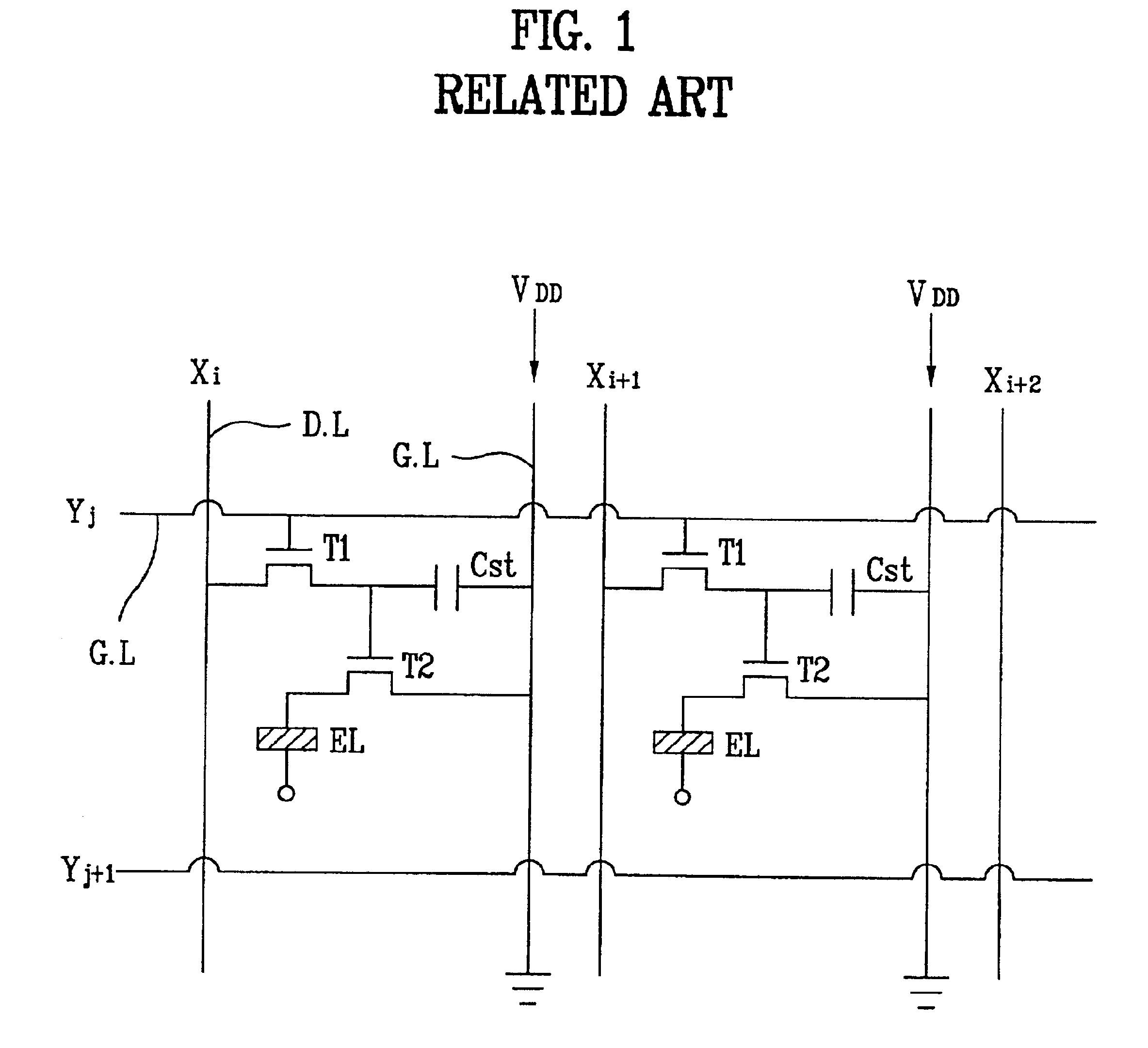
In FIGS. 3A and 3B, a ELD includes a transparent substrate 20 formed of glass, for example, on which light is transmitted and a picture screen is displayed, orthogonal gate lines (not shown) and data lines (not shown) cross each other on the transparent substrate 20 and having a plurality of pixel regions, a switching thin film transistor (TFT) 10 formed at a crossing point of the gate and data lines (not shown), a storage capacitor and light-emitting TFT respectively connected to an output terminal of the switching TFT 10, a...


PUM


Abstract

An electroluminescence display device includes a transparent substrate, a plurality of first electrodes formed on the transparent substrate, an electroluminescence layer and a plurality of second electrodes sequentially disposed on the first electrodes, a packaging plate having a plurality of protrusions formed at a side opposite to the plurality of second electrodes, an absorber contained within each protrusion, a plurality of semi-transparent films disposed on the packaging plate and each absorber, and an adhesive attaching the transparent substrate to the packaging plate to oppose each other.

Description

The present invention claims the benefit of Korean Patent Application No. P2000-69847 filed in Korea on Nov. 23, 2000, which is hereby incorporated by reference.BACKGROUND OF THE INVENTION1. Field of the InventionThe present invention relates to a flat display device, and more particularly, to an electroluminescence device (ELD) using organic and inorganic light emitting materials.2. Background of the Related ArtPresently, many different types of flat display devices are being used. Among the most popular are liquid crystal displays (LCDs), field emission displays (FEDs), electroluminescence devices (ELDs), and plasma display panels (PDPs). In particular, ELDs are formed in such a manner that an electrode is attached to both sides of an electroluminescence (EL) layer consisting of a hole transport layer, an light-emitting layer, and an electron transport layer. The ELD belongs to a group of next generation flat display devices because of its characteristic wide viewing angle, high a...

Claims


Application Information

Patent Timeline
IPC IPC(8): H01L51/52H01L51/50H05B33/04G09F9/30G09G3/30H01L27/32
CPCH01L51/5237G09G3/30G09G2300/0842H10K59/874H10K59/871H05B33/04H10K50/846H10K50/841
Inventor PARK, JAE YONGKIM, OCK HEE
Owner LG DISPLAY CO LTD
Why Eureka
Try Eureka