
Patsnap Eureka
For R&D, Patsnap Eureka makes reading and utilizing patents & technical documents easy.
Patsnap Eureka AIR
Designed for self-driven R&D workflows. Generate viable solutions, solve complex R&D challenges, empower your innovation with AI.

Patsnap Eureka Materials
Designed for material experts only. Revolutionize your material R&D, from search, analyze, to developing new materials.

TechResearch
Generate reliable direction feasibility study reports for your R&D in just a few steps.

TechSeek
Discover and master advanced knowledge NOW. Basics, ideas, possibilities, all at once.

TechMind
As an expert in R&D Theories, TechMind can generates customized viable solutions instantly.

TechRisk
Analyze your overall solution with one click, know your potential R&D risks in advance.

TechMonitor
Get weekly tech updates, stay abreast of the latest tech innovations and key insights.
Stylus input device
a technology of input device and input device, which is applied in the direction of instruments, computing, electric digital data processing, etc., can solve the problems of increased manufacturing cost and inconvenien
- Summary
- Abstract
- Description
- Claims
- Application Information
AI Technical Summary
Benefits of technology
Problems solved by technology
Method used
Image

Examples
Embodiment Construction
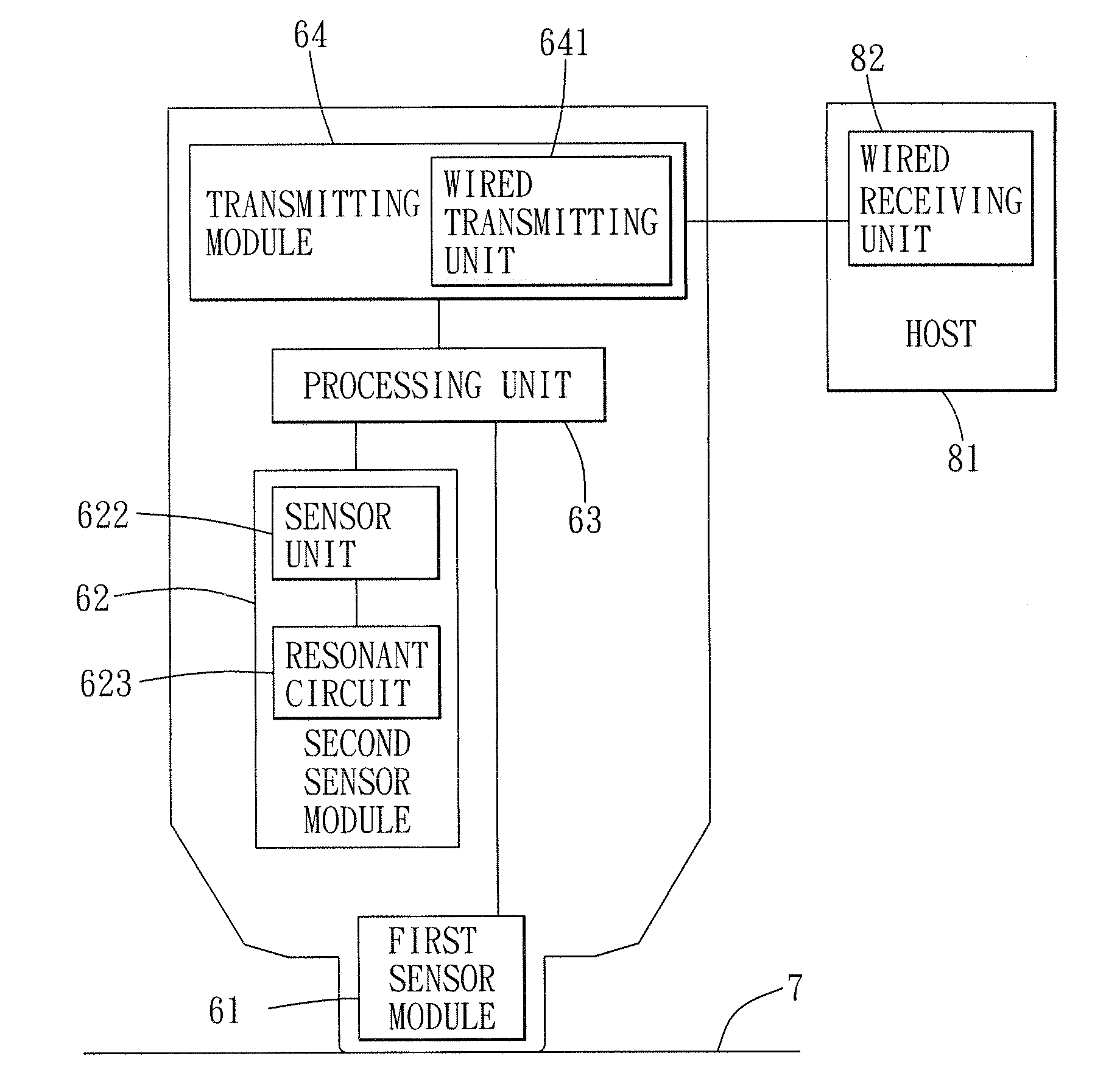
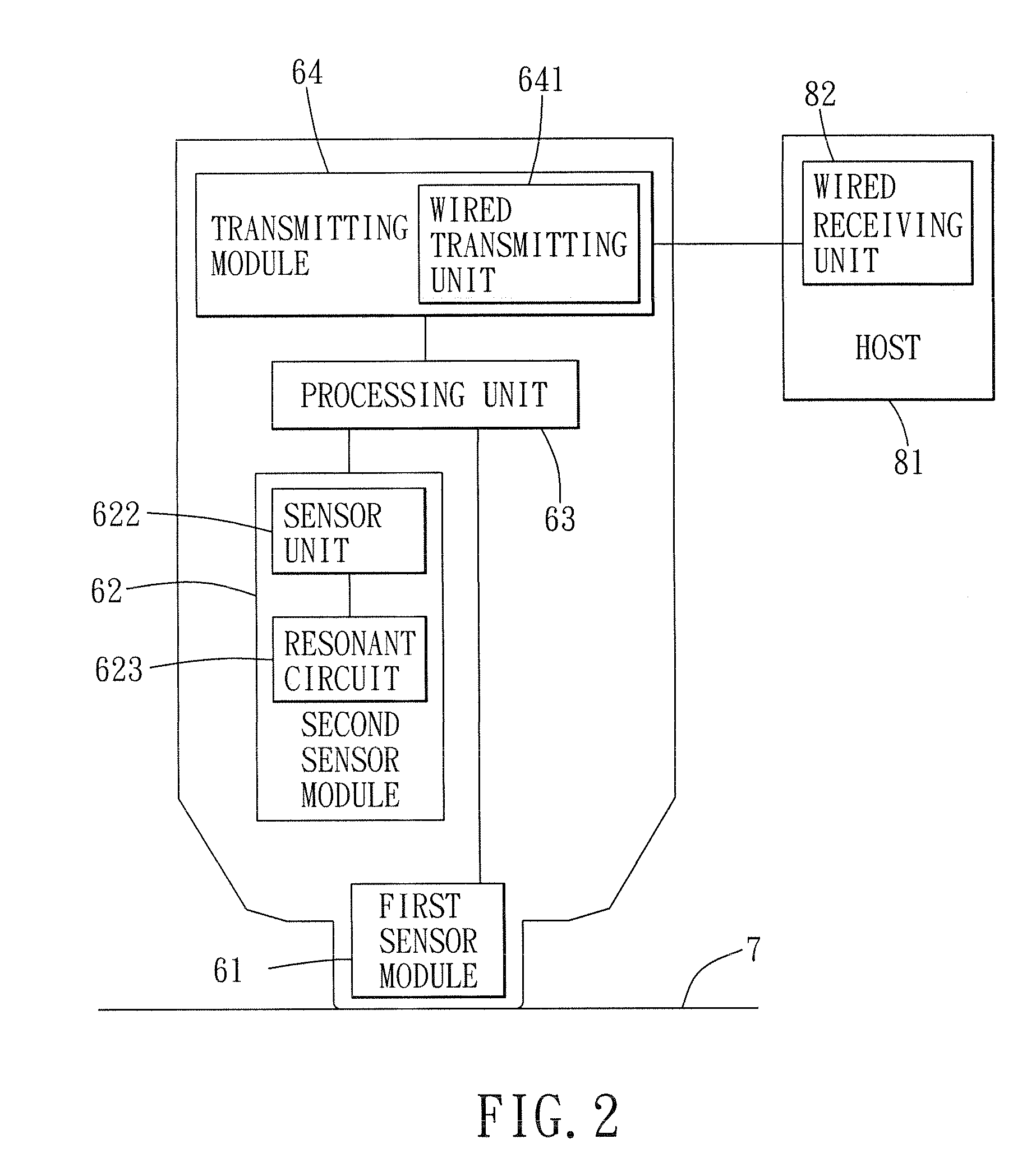
[0018]Referring to FIGS. 2, 4 and 5, a preferred embodiment of a stylus input device 100 operable for movement on a working surface 7 according to the present invention is shown to comprise a tubular grip 5, a surface-contacting member 32, a pivot joint 2, first and second sensor modules 61, 62, a processing unit 63, and a transmitting module 64.
[0019]The surface-contacting member 32 includes an end wall 322 having a contact surface 3220 for intimate contact with the working surface 7. The grip 5 defines an axis (A) and has a receiving space defining wall 11 that is formed at one end of the grip 5, that defines a receiving space 110 for receiving the pivot joint 2 therein, and that is provided with a pin 12 extending transverse to the axis (A) of the grip 5.
[0020]In this embodiment, the pivot joint 2 is a ball and socket joint disposed to connect pivotally the grip 5 to the surface-contacting member 32 and disposed to permit tilting of the grip 5 relative to the working surface 7 wh...
PUM
 Abstract
Description
Claims
Application Information
 - R&D Engineer
- R&D Manager
- IP Professional
- Industry Leading Data Capabilities
- Powerful AI technology
- Patent DNA Extraction
Browse by: Latest US Patents, China's latest patents, Technical Efficacy Thesaurus, Application Domain, Technology Topic, Popular Technical Reports.
© 2024 PatSnap. All rights reserved.Legal|Privacy policy|Modern Slavery Act Transparency Statement|Sitemap|About US| Contact US: help@patsnap.com