All metal leave N place armor joint form with joint fill retention

Inactive Publication Date: 2012-05-17
SMITH PATRICK MICHAEL
View PDF0 Cites 4 Cited by
  • Summary
  • Abstract
  • Description
  • Claims
  • Application Information

AI Technical Summary

Benefits of technology

[0009]This invention eliminates wooden forming labor and material tha

Problems solved by technology

The joint area is constantly exposed to fork lift traffic and continuous vibration of said traffic results in the joint filler compound bein

Method used


Image

  • All metal leave N place armor joint form with joint fill retention
  • All metal leave N place armor joint form with joint fill retention
  • All metal leave N place armor joint form with joint fill retention

Examples


Embodiment Construction

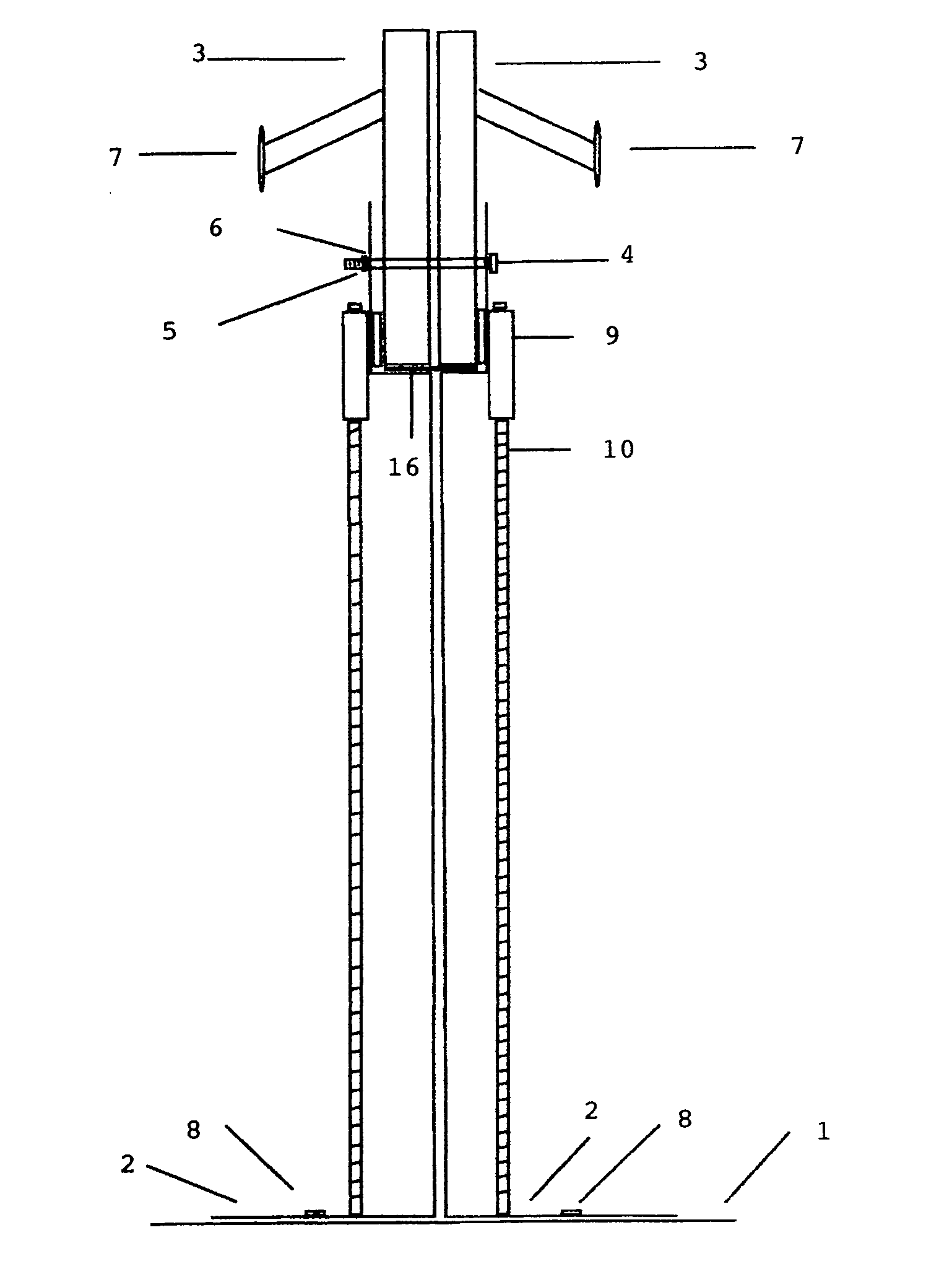
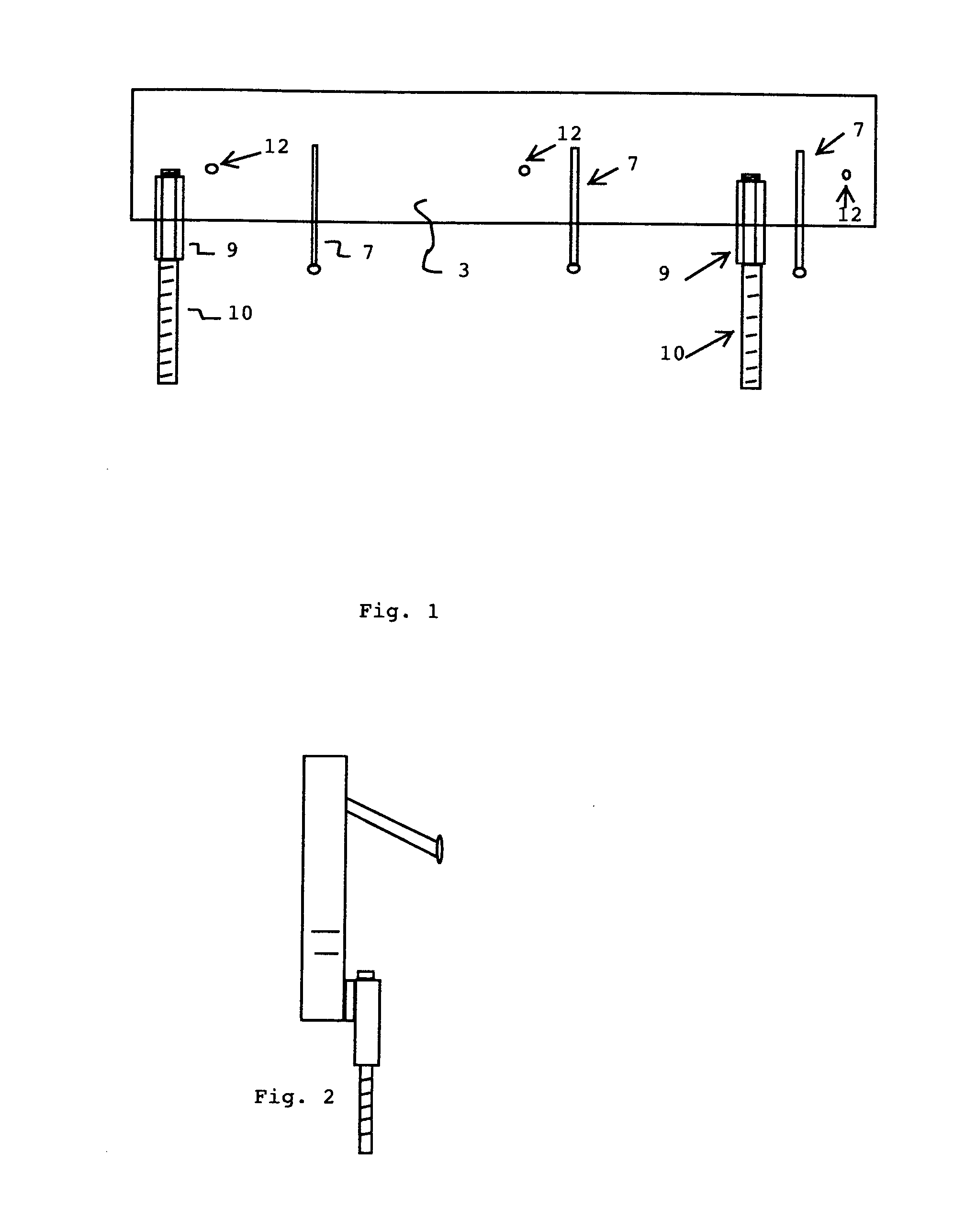
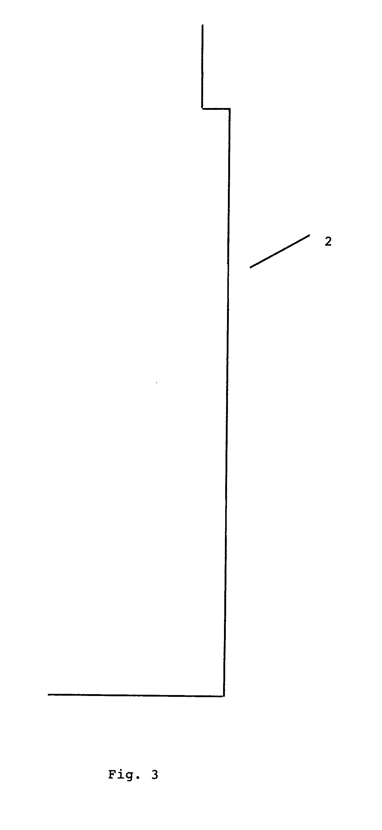
[0020]Referring to the drawing FIG. 5 this designates the metal base piece 1 to which will provide a support base for stabilization and to which the piece 2 as depicted in FIG. 3 shall be attached. This is accomplished by use of piece 8, a self tapping, self drilling screw, or rivet. Pieces 3 are then attached to piece 2 using neoprene bolts, nuts and washers, pieces 4, 5, 6, as depicted on FIG. 5, by inserting 4 thru the holes 12 in the pieces 7 and holes 13 in piece 2 as depicted FIG. 2 and FIG. 4. The neoprene bolts are designed to comprise during the concrete curing process and allow the armor joints to separate as the concrete floor cures. Pieces 5 and 6 are then used to secure pieces 7 to piece 2.

[0021]Pieces 3 is a fabricated assembly by attaching a stub, piece 7 at 30 degrees as depicted on FIG. 1. by welding. Piece 9 is a threaded coupling which is also attached by welding. Piece 10 is a threaded bolt which is threaded thru piece 8 and provides an adjustment mechanism for h...


PUM

PropertyMeasurementUnit
Fractionaaaaaaaaaa
Shrinkageaaaaaaaaaa
Stabilityaaaaaaaaaa

Description

CROSS-REFERENCE TO ALL RELATED APPLICATIONS[0001]Not ApplicableSTATEMENT REGARDING FEDERALLY SPONSORED RESEARCH OR DEVELOPMENT[0002]Not Applicable.NAMES OF PARTIES TO ADJOINT RESEARCH AGREEMENT[0003]Not ApplicableREFERENCE TO SEQUENCE LISTING, A TABLE, OR COMPUTER PROGRAM LISTING COMPACT DISC APPENDIX[0004]Not ApplicableBACKGROUND OF INVENTION[0005]Due to the required labor and material required to form and place an armored joint with wooden forms in a concrete floor this invention eliminates these steps by providing a one step set and alignment of the armor joint. The form is left in place and requires no additional labor to remove conventional wooden forming materials.[0006]The joint area is constantly exposed to fork lift traffic and continuous vibration of said traffic results in the joint filler compound being compromised and a settling effect takes place resulting with the joint fill dropping and leaving an exposed “gap” between the armor joints.[0007]This invention provides a...

Claims


Application Information

Patent Timeline
IPC IPC(8): E04B2/86
CPCE01C11/126E01C11/08
Inventor SMITH, PATRICK MICHAEL
Owner SMITH PATRICK MICHAEL
Why Eureka
Try Eureka