
Ventilation fan

a technology of ventilation fan and fan body, which is applied in the direction of magnetic circuit, mechanical energy handling, liquid fuel engine components, etc., can solve the problems of limiting the miniaturization of such a conventional ventilation fan of inner rotor type, and the strength problem of the outer rotor type fan, so as to achieve stable holding, maintain the effect of holding strength and minimal vibration

Inactive Publication Date: 2012-05-17
NIDEC CORP
View PDF7 Cites 9 Cited by
  • Summary
  • Abstract
  • Description
  • Claims
  • Application Information

AI Technical Summary

Benefits of technology

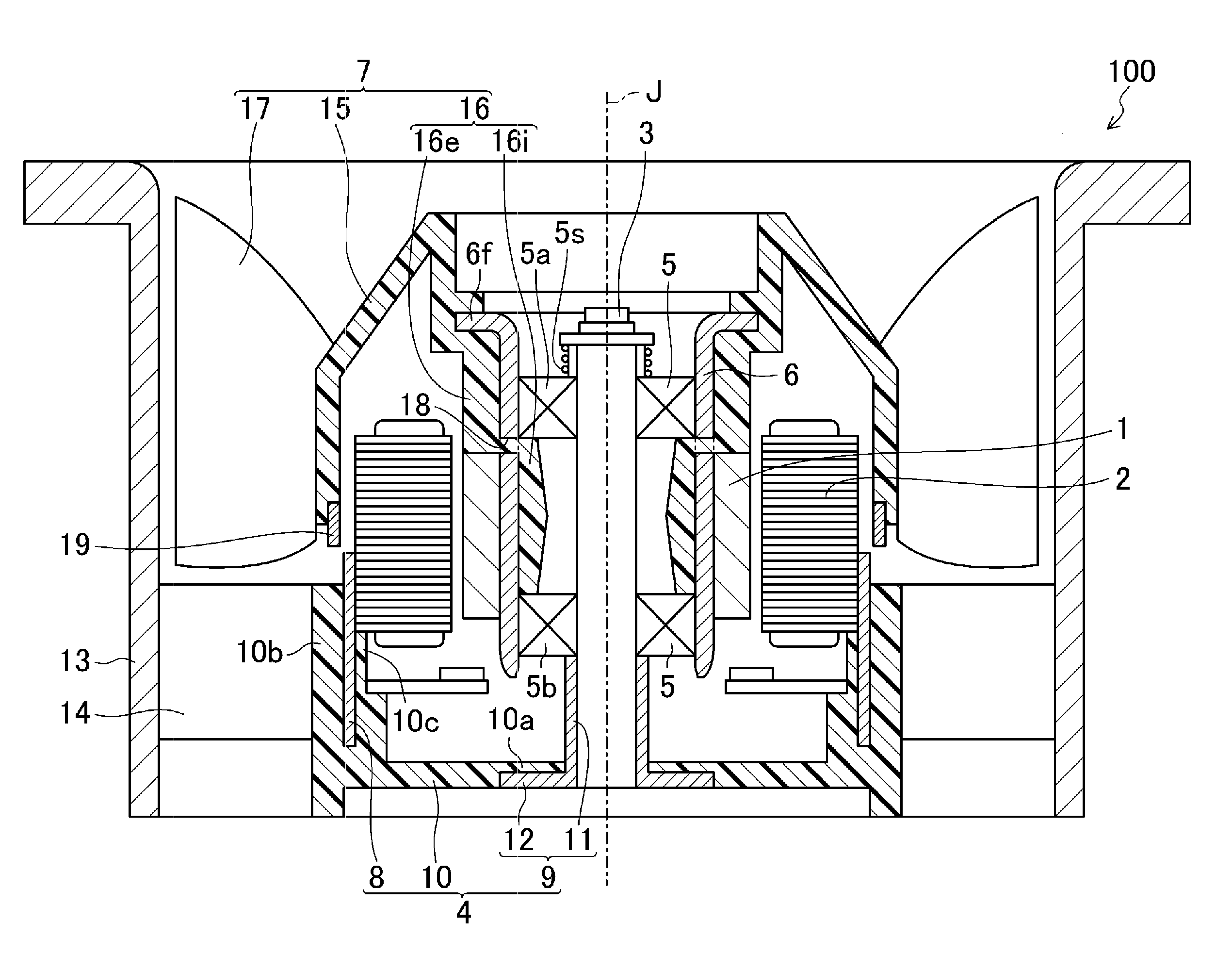
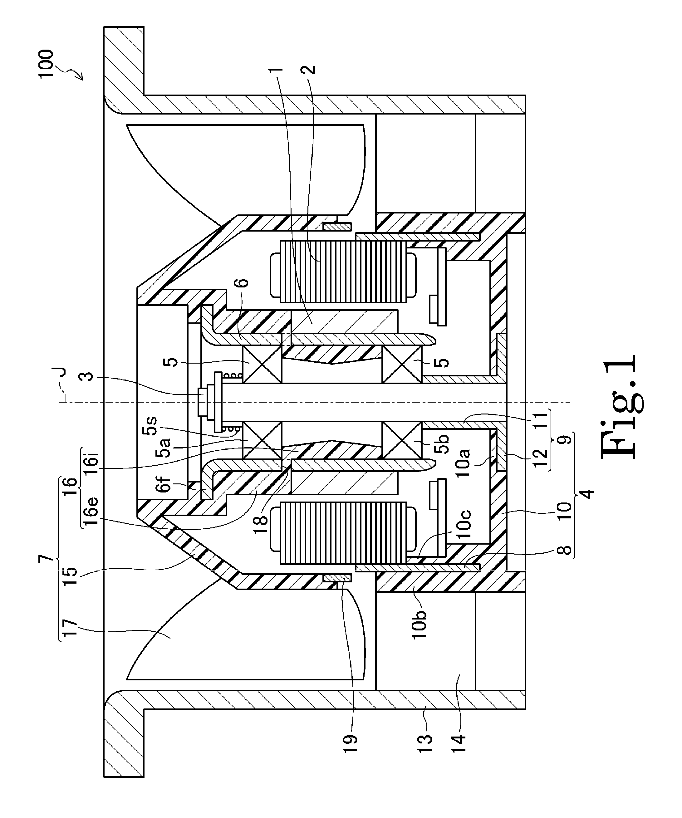
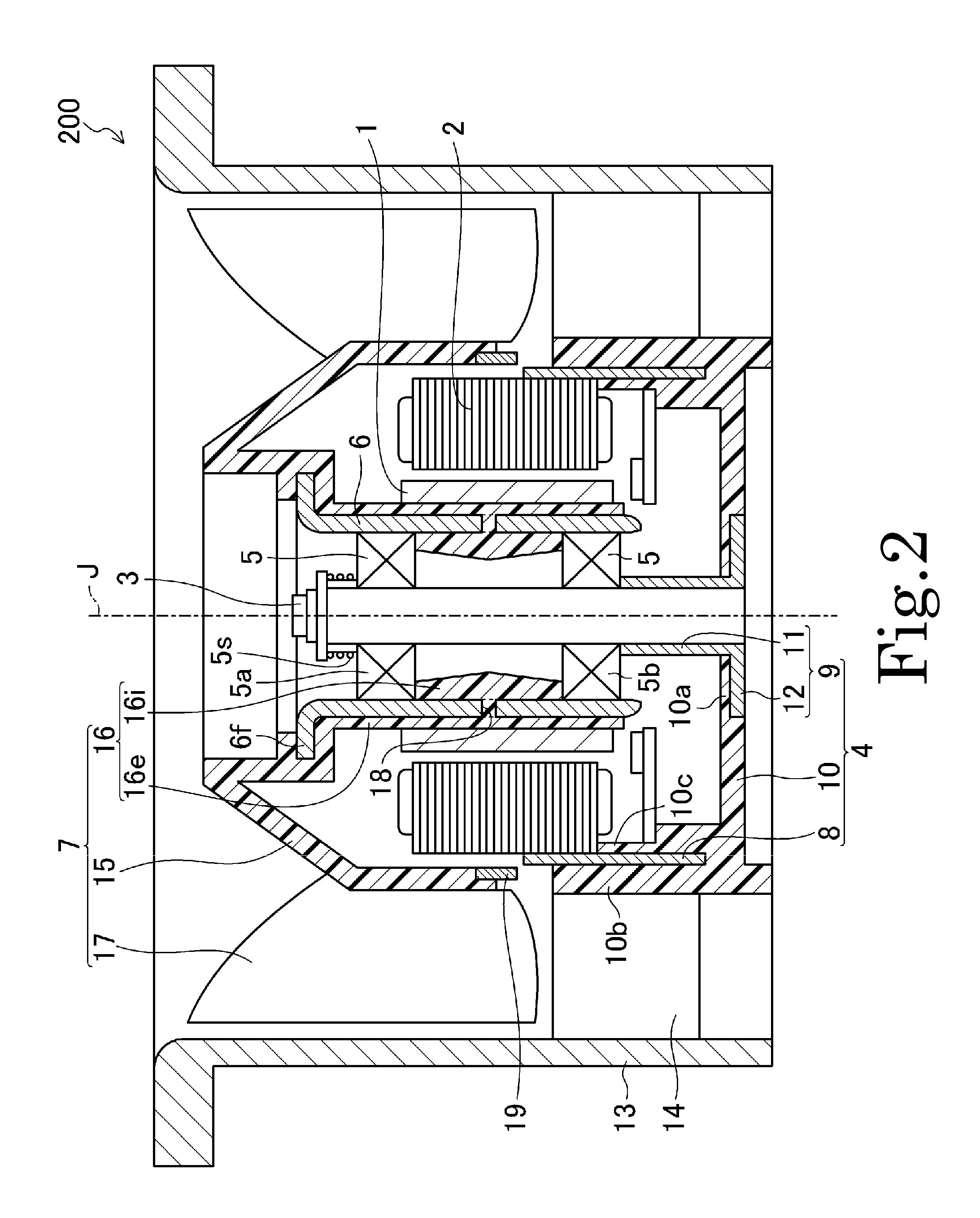
[0008]Preferred embodiments of the present invention provide a ventilation fan in which a shaft defining a fixed axis fixed to a motor supporting portion can be stably held even when the fan performs high-speed rotation, and of which the size in the axial direction can be reduced.
[0011]With the above-described configuration, the shaft is preferably held by a shaft holding portion made of, for example, a metal member, and the shaft holding portion includes a cylindrical portion into which the shaft is inserted and a shaft holding flange portion extending from the cylindrical portion to the outside in the radial direction. Accordingly, even when the ventilation fan performs high-speed rotation, the shaft holding portion can stably hold the shaft, and the holding strength can be maintained.
[0012]According to the preferred embodiments of the present invention, even when the ventilation fan performs high-speed rotation, the shaft is stably held to the motor supporting portion through the shaft holding portion. Therefore, it is possible to provide a ventilation fan with minimal vibrations that can also be miniaturized.

Problems solved by technology

However, such an outer rotor type fan may possess a strength problem due to the vibration in high-speed rotation because the moment of inertia in rotation is high.
However, since it is necessary to provide a certain space between the rotor holding portion as a rotating body and the bearing holding portion as a non-rotating body, there is a limit to miniaturization of such a conventional ventilation fan of inner rotor type with the above-described configuration.

Method used


Image

  • Ventilation fan
  • Ventilation fan
  • Ventilation fan

Examples


Embodiment Construction

[0019]Referring to FIGS. 1 through 5, preferred embodiments of the present invention will be described in detail. The ventilation fans according to preferred embodiments of the present invention are preferably axial fans in which air flows in a direction along the axial direction. It should be noted that in the following description of preferred embodiments of the present invention, for convenience of explanation, an axial direction indicates a direction parallel or substantially parallel to a shaft center of rotation of the ventilation fan, and a radial direction indicates a direction perpendicular or substantially perpendicular to the shaft center of rotation of the ventilation fan. The air suction side of the ventilation fan is described as being up, and the air exhausting side thereof is described as being down. However, this is merely for convenience of explanation and an installed device could have an air suction side being down and an air exhausting side being up.

[0020]Prefer...


PUM


Abstract

In a ventilation fan of inner rotor type in which a shaft is fixed to a motor supporting portion, the shaft is held by a shaft holding portion preferably provided by, for example, a metal member. The shaft holding portion includes a cylindrical portion which is fixed to a resin of the motor supporting portion preferably by being embedded through insert molding and into which the shaft is inserted, and a shaft holding flange portion extending outwards in the radial direction from either one of an upper end or a lower end of the cylindrical portion.

Description

BACKGROUND OF THE INVENTION[0001]1. Field of the Invention[0002]The present invention relates to a ventilation fan and more specifically to a ventilation fan preferably used for cooling electronic equipment, for example, and for other purposes.[0003]2. Description of the Related Art[0004]In recent years, as miniaturization of electronic equipment advances, the density of components in the electronic equipment increases, and thus, the amount of heat generated by the electronic equipment increases. For this reason, a ventilation fan which is mounted on such miniaturized electronic equipment for the purpose of radiating the heat from the electronic equipment is required to be further miniaturized, and to also have a higher cooling ability. In order to satisfy such requirements for the ventilation fan, it is suggested that the rotation speed of the fan may be increased, so as to increase the amount of air flowing through the inside of the electronic equipment.[0005]As a fan motor for dr...

Claims


Application Information

Patent Timeline
Patent Type & Authority Applications(United States)
IPC IPC(8): F01D5/14H02K1/06
CPCF04D19/002F04D25/0606H02K7/14H02K1/30H02K5/08H02K1/187
Inventor KITAMURA, JUMPEI
Owner NIDEC CORP
Learn More