Estimating positions of a device and at least one target in an environment

a technology of environment and device, applied in the direction of process and machine control, electrical apparatus, instruments, etc., can solve the problems of reducing control performance, increasing computational complexity, and unlikely computationally feasible operation in a complex environmen

Active Publication Date: 2012-05-17
BAE SYSTEMS PLC
View PDF2 Cites 13 Cited by
  • Summary
  • Abstract
  • Description
  • Claims
  • Application Information

AI Technical Summary

Benefits of technology

[0045]Whilst the invention has been described above, it extends to any inventive combination of features set out above or in the following description. Although illustrative embodiments of the invention are described in detail herein with reference to the accompanying drawings, it is to be understood that the invention is not limited to these precise embodiments. As such, many modifications and variations will be apparent to practitioners skilled in the art. Furthermore, it is contemplated that a particular feature described either individually or as part of an embodiment can be combined with other individually described features, or parts of other embodiments, even if the other features and embodiments make no mention of the particular feature. Thus, the invention extends to such specific combinations not already described.

Problems solved by technology

One of the most significant disadvantages of using a SLAM-type approach to maintain the information is that the computational complexity increases as a function of the square of the number of landmarks, and the EKF eventually (and necessarily) introduces inconsistencies in the estimates.
While this may be sufficient for a relatively simple, structured environment, operation in a complex environment is unlikely to be computationally feasible.
In this case the control loop is limited to a maximum rate that will be determined by the update rate of the SLAM algorithm, resulting in decreased control performance as the environmental representation becomes increasingly complex, which is in direct conflict with desired characteristics.

Method used


Image

  • Estimating positions of a device and at least one target in an environment
  • Estimating positions of a device and at least one target in an environment
  • Estimating positions of a device and at least one target in an environment

Examples


Embodiment Construction

[0046]The invention may be performed in various ways, and, by way of example only, embodiments thereof will now be described, reference being made to the accompanying drawings in which:

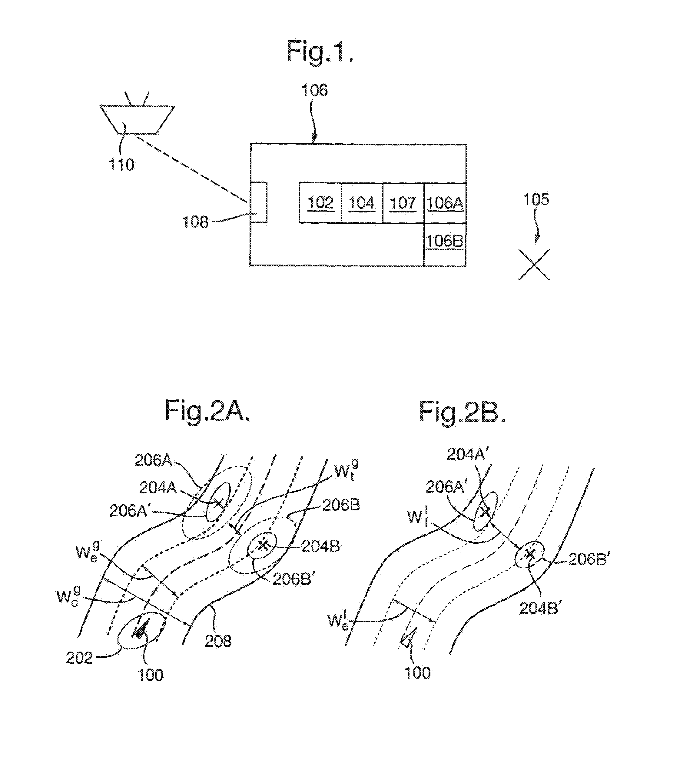
[0047]FIG. 1 is a block diagram of a vehicle fitted with at least one onboard sensor;

[0048]FIGS. 2A and 2B illustrate schematically a vehicle using global and local measurements, respectively, in the context of path-based motion control;

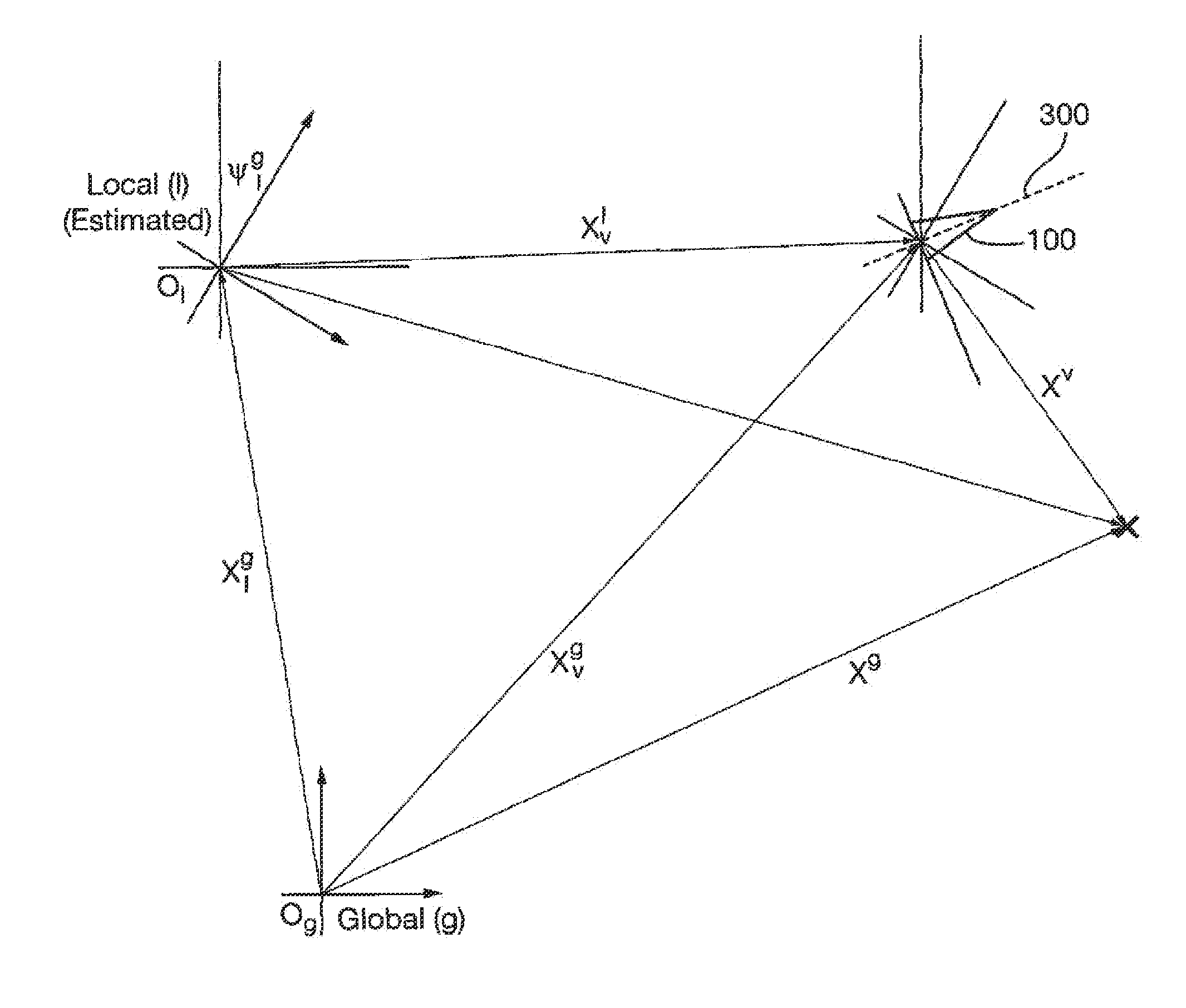
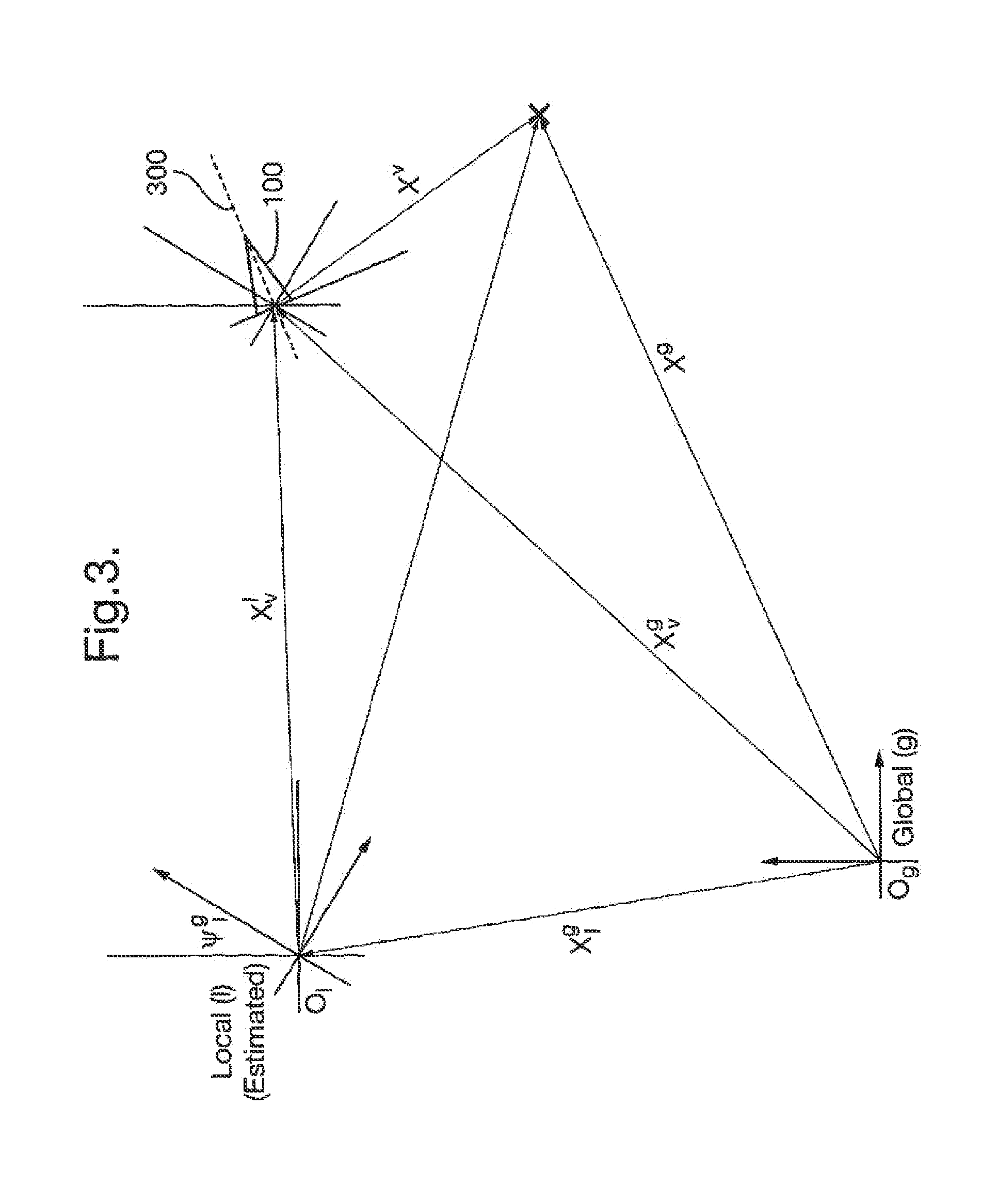
[0049]FIG. 3 shows a construction including an estimated local coordinate reference frame and a global coordinate reference frame;

[0050]FIG. 4 shows a construction including an “error-free” local coordinate reference frame, and

[0051]FIGS. 5A and 5B are flowcharts showing operations performed by computing device onboard the vehicle in order to estimate positions of the vehicle and at least one target.

[0052]FIG. 1 shows a vehicle 100 that is fitted with a computing device including a processor 102 and memory 104. The vehicle will also include other conventional features,...


PUM


Abstract

A method/system for estimating a state of a device and at least one target in an environment. The process involves computing a state vector using an error state form of the position of the device in a local coordinate reference frame.

Description

BACKGROUND TO THE INVENTION[0001]The present invention relates to estimating a position of a device in an environment and to estimating positions of a device and at least one target.[0002]Autonomous planning of vehicular manoeuvres often involves two distinct types of information in order to estimate the position of a vehicle and objects in its vicinity. Global information is provided in a fixed coordinate system external to the vehicle, e.g. the coordinate system used by GPS, and local information is provided with respect to a coordinate system that can move with the vehicle. At its simplest, global information is data provided by “external” systems where a shared reference frame is required to communicate the data, while local information is available in a relative form and may need no external reference knowledge.[0003]Traditional approaches map the local information into global coordinates and use that information to achieve tasks such as mapping, or planning and executing manoe...

Claims


Application Information

Patent Timeline
Patent Type & Authority Applications(United States)
IPC IPC(8): H04W24/00
CPCG05D1/024G05D1/0257G05D1/0272G05D2201/0207G05D1/0278G05D1/028G05D1/0274
Inventor DAY, PETER STEPHENGROVER, RICHARD FRANCIS
Owner BAE SYSTEMS PLC
Why Eureka
Try Eureka