Fine particle separator
a technology of fine particles and separators, applied in the direction of separation process, filtration separation, moving filter element filter, etc., can solve the problems of difficult minimization of mechanical oscillation mechanisms and ultrasonic oscillation mechanisms, serious damage to fine particles, poor energy efficiency of ultrasonic oscillation mechanisms, etc., and achieve the effect of reducing the amount of clogging
- Summary
- Abstract
- Description
- Claims
- Application Information
AI Technical Summary
Benefits of technology
Problems solved by technology
Method used
Image

Examples
first embodiment
1. Fine Particle Separator
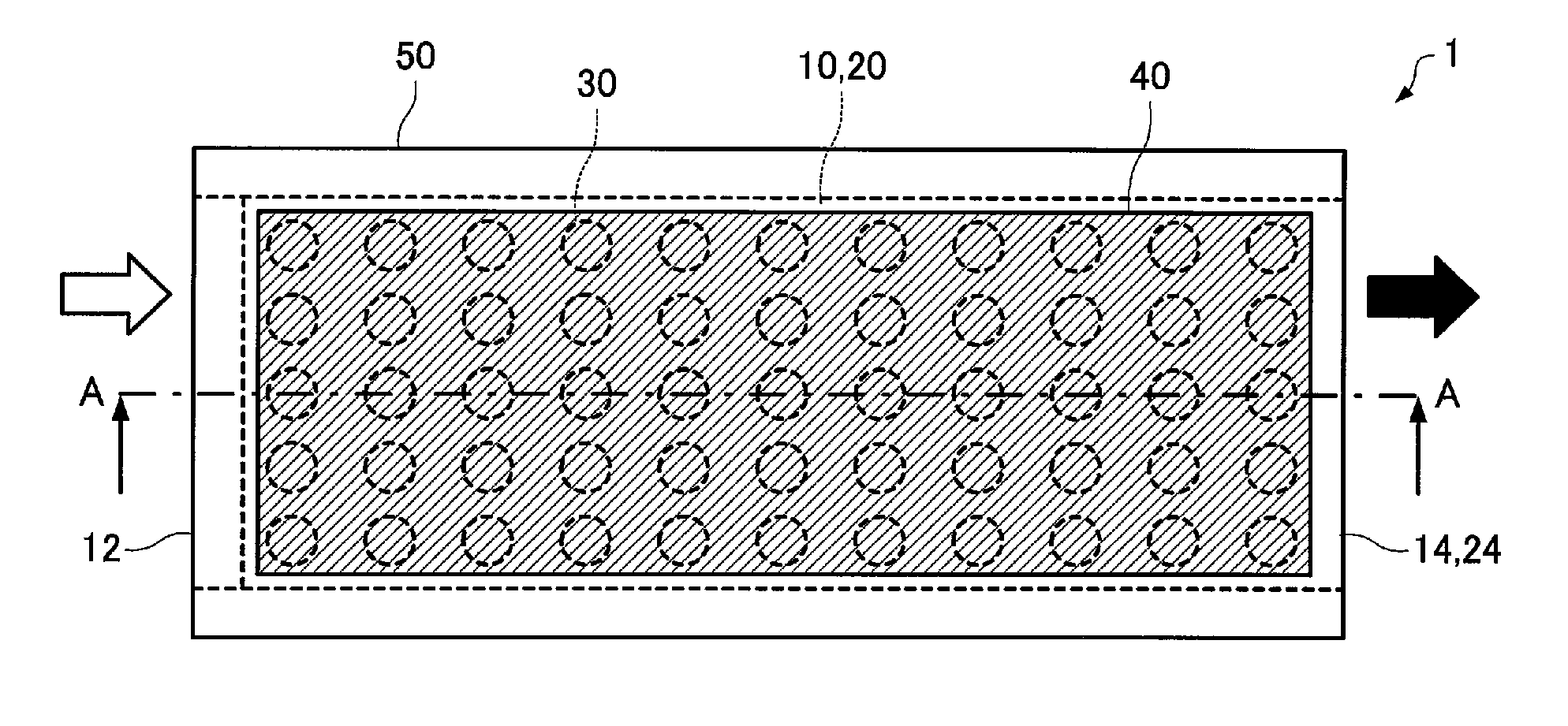
[0042]FIG. 1A is a plan view schematically representing a fine particle separator 1 according to First Embodiment. FIG. 1B is a cross sectional view taken at line A-A in FIG. 1A.
[0043]The fine particle separator 1 according to the present embodiment includes a channel 10 with an inlet 12, a chamber 20, a filter 30 in communication with the channel 10 and the chamber 20, and a piezoelectric element 40 that vibrates the filter 30.
[0044]The inlet 12 provided for the channel 10 is an opening through which a liquid-phase and solid-phase turbid solution or a dispersion of solid particles in liquid is introduced. Specifically, the channel 10 serves as a channel for flowing liquid or the like from the inlet 12 to the filter 30.
[0045]The channel 10 may also include an outlet 14 through which a liquid-phase and solid-phase turbid solution or a dispersion of solid particles in liquid is discharged. Specifically, the channel 10 may serve as a channel for flowing liquid...
second embodiment
2. Fine Particle Separator
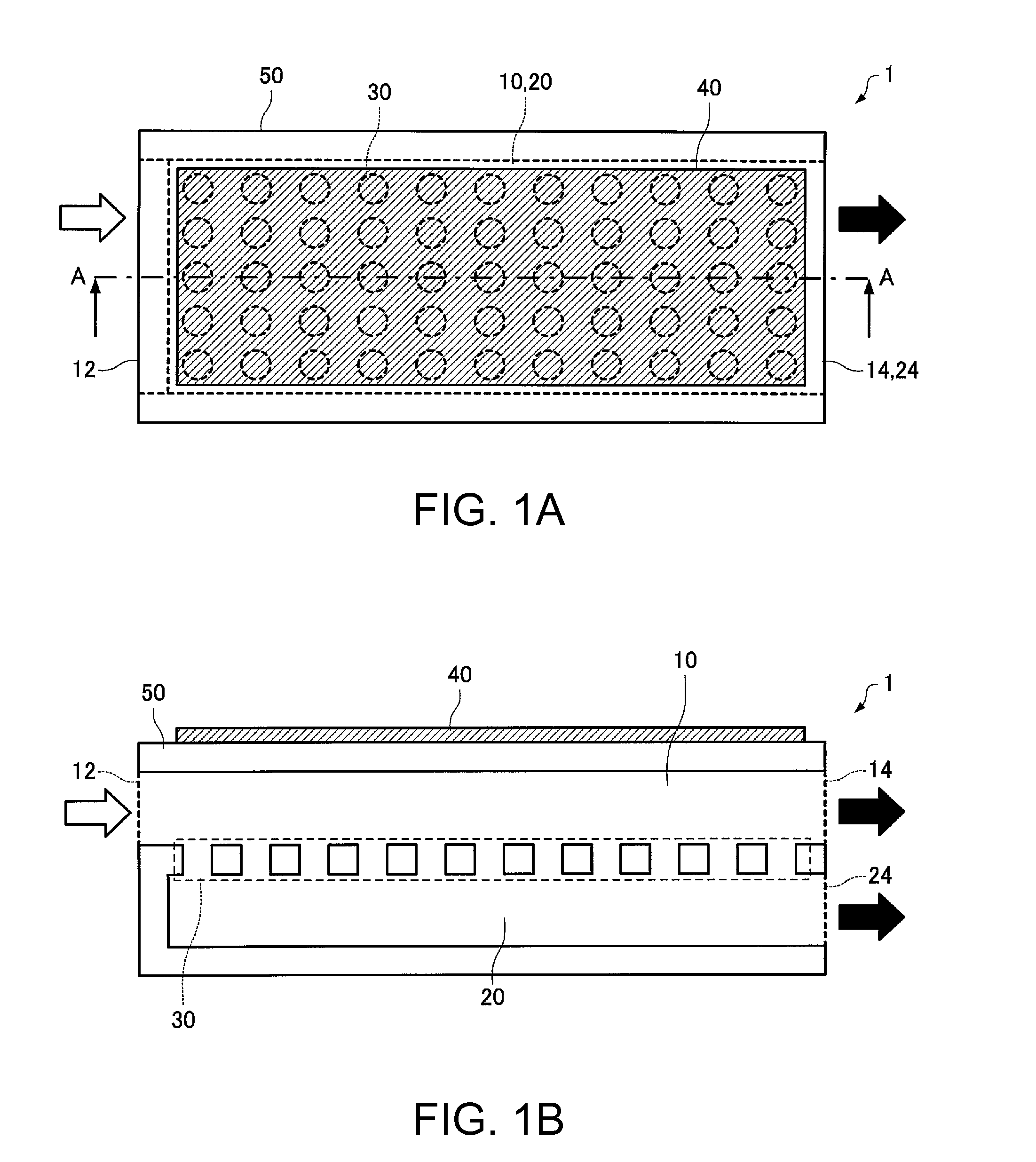
[0059]FIG. 2A is a plan view schematically representing a fine particle separator 2 according to Second Embodiment. FIG. 2B is a cross sectional view taken at line A-A in FIG. 2A.
[0060]The fine particle separator 2 according to Second Embodiment includes a support member 60 that supports the piezoelectric element 40 by connecting a part of the piezoelectric element 40 to the inner wall surface of the channel 10. The piezoelectric element 40 is provided in the channel 10.
[0061]In the example illustrated in FIGS. 2A and 2B, the support member 60 is configured to support the piezoelectric element 40 by connecting the piezoelectric element 40 at the portions near the lengthwise end portions to the channel forming member 50 representing the inner wall surface of the channel 10. Preferably, the support member 60 is formed using a material having high vibration absorption capability. Examples of such materials include rubber materials (such as elastomers).
[0062]In...
third embodiment
3. Fine Particle Separator
[0063]FIG. 3A is a plan view schematically representing a fine particle separator 3 according to Third Embodiment. FIG. 3B is a cross sectional view taken at line A-A in FIG. 3A.
[0064]In the fine particle separator 3 according to Third Embodiment, the piezoelectric element 40 is provided in the channel 10, in contact with the filter 30. In the example illustrated in FIGS. 3A and 3B, the piezoelectric element 40 is laminated on the filter 30 and bonded on the side of the channel 10. Further, in the example of FIGS. 3A and 3B, the piezoelectric element 40 has through holes in communication with the through holes of the filter 30.
[0065]The fine particle separator 3 according to Third Embodiment can directly vibrate the filter 30 with the piezoelectric element 40. Clogging can thus be reduced with an even smaller vibration energy.
[0066]Further, the fine particle separator 3 according to Third Embodiment can be produced using a simple method, for example, by lam...
PUM
| Property | Measurement | Unit |
|---|---|---|
| diameter | aaaaa | aaaaa |
| diameter | aaaaa | aaaaa |
| ultrasonic oscillation | aaaaa | aaaaa |
Abstract
Description
Claims
Application Information
 - R&D
- Intellectual Property
- Life Sciences
- Materials
- Tech Scout
- Unparalleled Data Quality
- Higher Quality Content
- 60% Fewer Hallucinations
Browse by: Latest US Patents, China's latest patents, Technical Efficacy Thesaurus, Application Domain, Technology Topic, Popular Technical Reports.
© 2025 PatSnap. All rights reserved.Legal|Privacy policy|Modern Slavery Act Transparency Statement|Sitemap|About US| Contact US: help@patsnap.com