Cable routing device

a routing device and cable technology, applied in the direction of electrical equipment, pipe supports, pipe/joints/fittings, etc., can solve the problems of high logistic cost, high cost of operation, and high cost of assembly time, and achieve the effect of easy and rapid transformation

Inactive Publication Date: 2012-05-24
CQFD COMPOSITES
View PDF12 Cites 6 Cited by
  • Summary
  • Abstract
  • Description
  • Claims
  • Application Information

AI Technical Summary

Benefits of technology

[0009]The object of the present invention is to find a remedy to these drawbacks by proposing a cable routing device substantially made from synthetic materials and allowing easy and rapid transformation of the cable routing device from a planar or L-shaped configuration beneficial for its making or for its storage and its transport into a U-shaped configuration for its installation on site.
[0028]According to another feature of the present invention, said rounded portion of each hook tapers from a base part of said rounded portion connected to said base to a free end of said rounded portion, and said base part is larger and / or thicker than a window of said side post, thus allowing a play between said rounded portion and said window when said side post is in said first position and performing a tightening without any play between said rounded portion and said window when said side post is in said second position.
[0033]The bars may include side stabilizers bearing upon a surface of the pivoting side post allowing the bars to be blocked perpendicularly to the longitudinal axis of the cable route and preventing any longitudinal deformation of the latter during use.

Problems solved by technology

However, these cable routing devices occupy a significant volume during their storage and their transport up to the area of their installation, which causes high logistic costs.
However in order to maintain the cable route jointed in its U-shaped configuration with view to installing it on site, it is necessary to manually place or actuate right-angled or ring-shaped blocking components at each mesh of the wire mesh between the side posts and the base which makes the operation tedious and costly in assembly time.
Additionally, metal cable routing devices have a great weight and may have sharp edges, after cutting, which damage the cables or injure the installers.
Moreover, they are electrically conductive, which imposes that each component of the cable routing device be connected to the ground which considerably increases the installation costs.

Method used


Image

  • Cable routing device
  • Cable routing device
  • Cable routing device

Examples


first embodiment

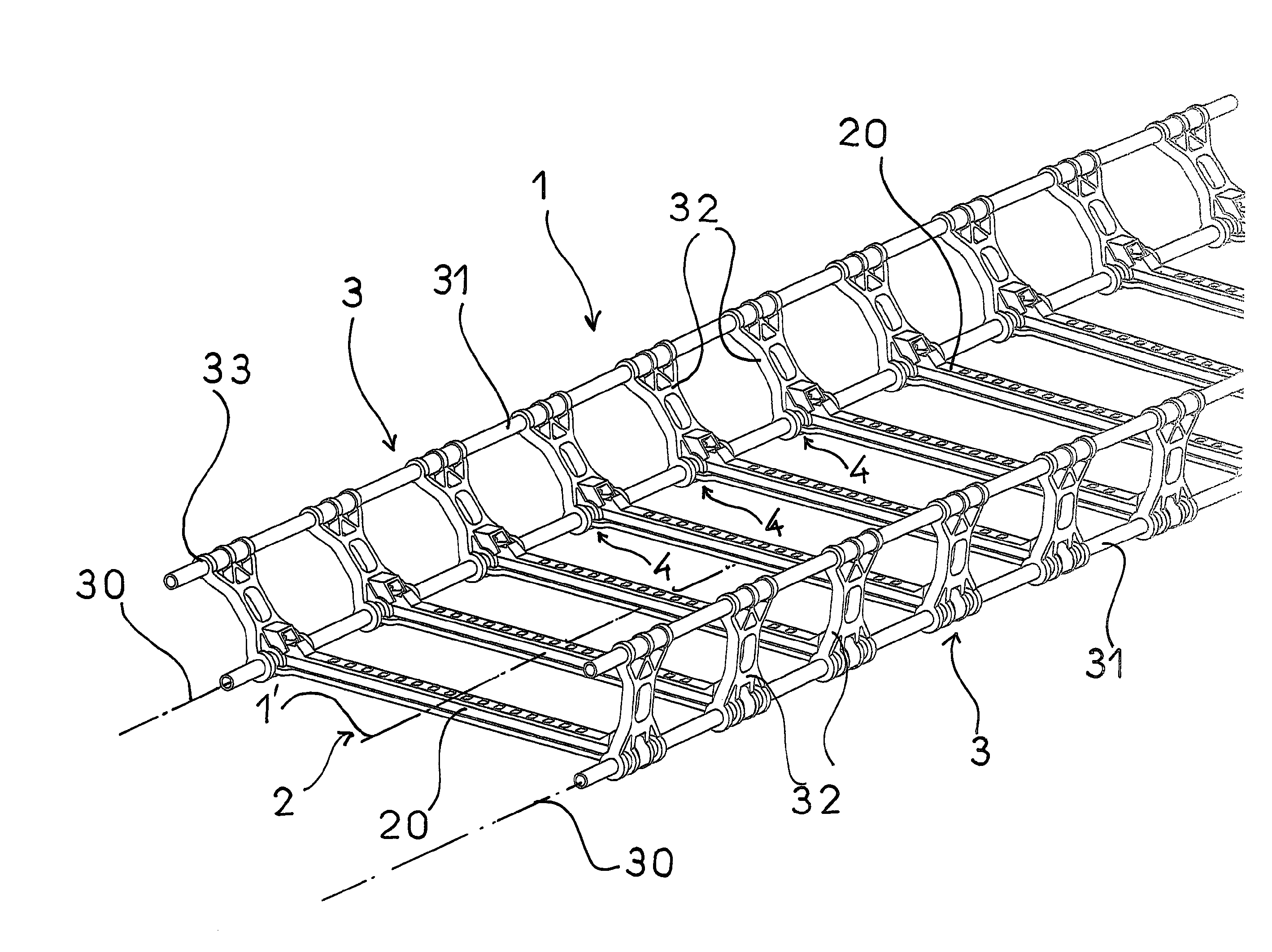
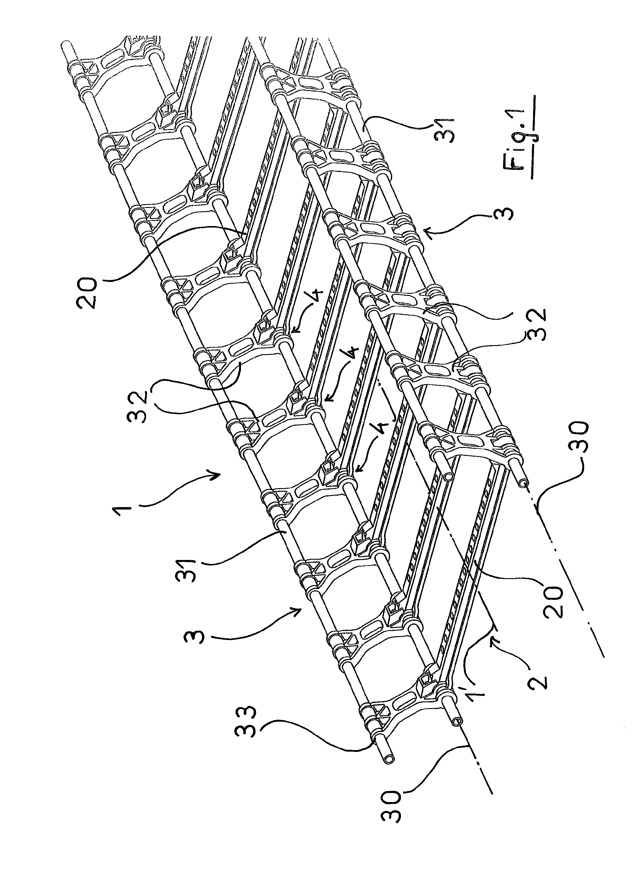
[0050] shown of FIGS. 1 and 2, a side post 3 consists of two parallel rods 31 preferably made in a composite material and connected to each other through connecting parts 32 with a globally rectangular shape, regularly spaced out and located in the plane formed by the two straight rods 31. A connecting part 32 is made from a reinforced plastic material and includes at each of its ends, a transverse orifice 33 intended to respectively receive the straight rods 31, one of which materializes the axis of rotation 30 of the side post 3 with the base 2.

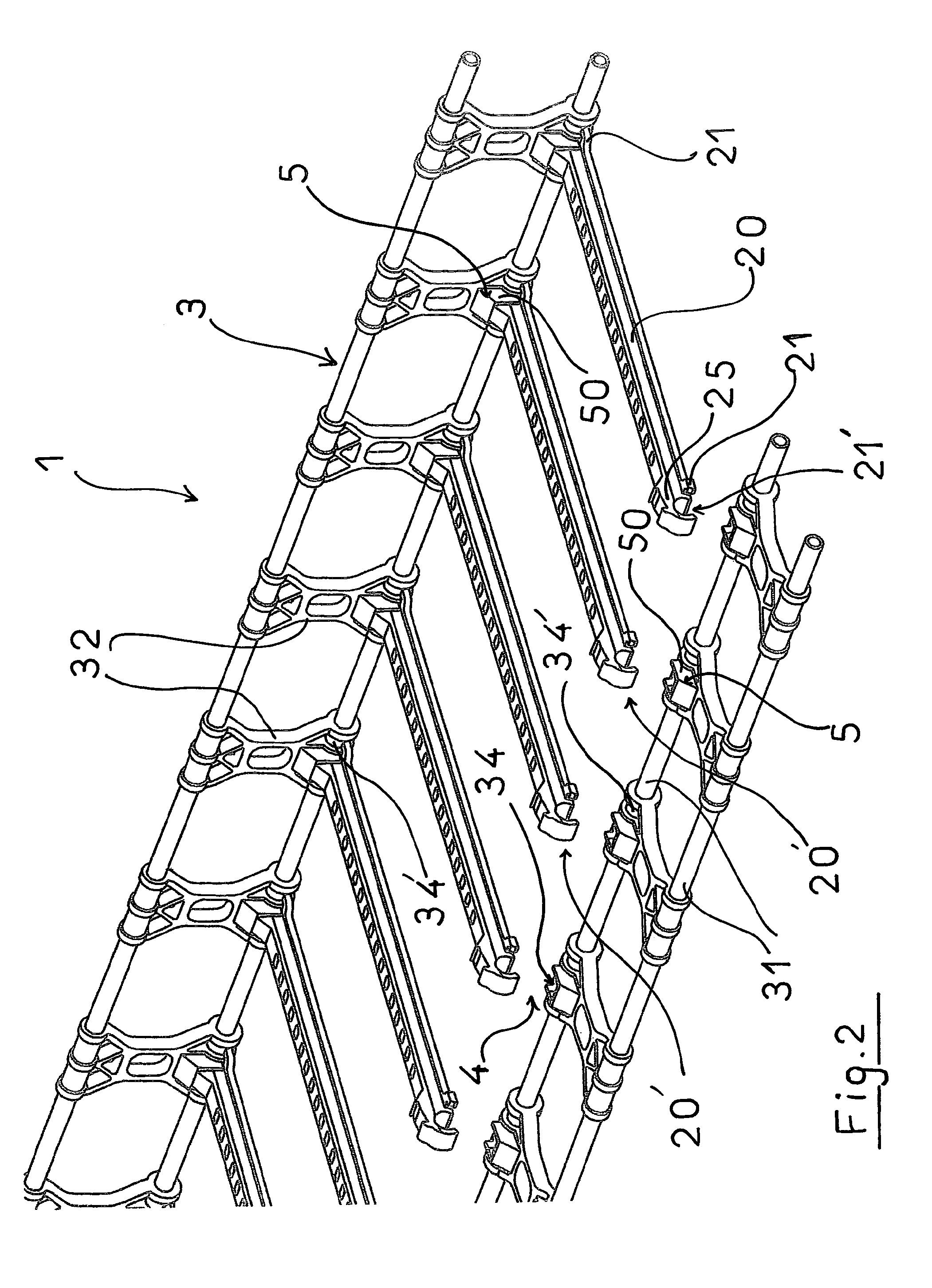
[0051]It may also be seen that each connecting part 32 includes, at the transverse orifice intended to be crossed by the rod 31 forming the axis of rotation 30 of the side post 3, a window 34 with which the corresponding free end 20′ of a bar 20 may be hemmed into a window 34 around the rod 31 so as to ensure the joint between the base 2 and the side post 3 and to limit the possibilities of longitudinal movement of said base relative to sai...

second embodiment

[0069]FIG. 7, FIG. 8 and FIG. 9 show the device, in which the structure 1 comprises two side posts 6 made in a single piece by profile-shaping, which each appear as an elongated rectangular panel including windows 60 intended to closely receive the hooks 20′ of bars 20 forming the base 2 of the structure 1.

[0070]One of the longitudinal edges of each side post 6 is rounded and forms a longitudinal portion 61 forming the axis of rotation 30 about which the side post 6 pivots. The side post 61 delimits one of the sides of the windows 60, on which are engaged the free ends 20′ of the bars 20 of the base 2 hemmed into the windows 60 so as to secure the side posts 6 to the base 2, as this may be seen in FIG. 9, and to allow pivoting of the side posts 6 about the axis of rotation 30 relatively to the base 2.

[0071]Maintaining the side posts 6 in an angular position perpendicular to the base 2 is achieved by a tab 63 perpendicularly and longitudinally secured to the internal face of the side...


PUM


Abstract

Device for routing cables, more particularly intended for routing and distributing electric cables having an elongated shape (1) with a U-shaped cross-section including an assembly of two side posts (3) forming the arms of the U and of a base (2) forming the bottom of the U. The side posts (3) and the base (2) are made from a composite material and / or a strengthened plastic material and in that at least one side post (3) is pivotally mounted while being jointed to the base (2) about an axis of rotation (30) by at least one hinge (4) and in that it comprises snap-coupling devices (35,26,63,7) and abutment devices (22,23,38,29,27) capable of locking the side post perpendicularly to said base (2) under the action of its rotation.

Description

CROSS REFERENCE TO RELATED APPLICATION[0001]This application is a continuation-in-part of U.S. patent application Ser. No. 12 / 664,896 filed Dec. 16, 2009, pending, which is a national stage entry of PCT / FR2008 / 000827 filed Jun. 16, 2008, under the International Convention claiming priority over French Application No. 0704390 filed Jun. 20, 2007.FIELD OF THE INVENTION[0002]The present invention is a device for routing cables, more particularly intended for routing and distributing electric cables.BACKGROUND OF THE INVENTION[0003]Present cable routings comprise an elongated structure with a U-shaped cross-section, inside which the cables are laid and optionally attached, and either made from an assembly of metal components forming a base and side posts, commonly called <<cable ladders>>, intended to support cables with a weight of the order of 100 kg / m with supporting distances of the order of 3-4 meters, or as a one-piece structure in solid or open worked metal sheet or e...

Claims


Application Information

Patent Timeline
Patent Type & Authority Applications(United States)
IPC IPC(8): F16L3/22
CPCH02G3/0456H02G3/045
Inventor CHAUZU, FRANKCHAUZU, RENE
Owner CQFD COMPOSITES
Why Eureka
Try Eureka