Apparatus and method for locking a valve

a technology for locking valves and devices, applied in mechanical apparatus, metal working apparatus, manufacturing tools, etc., can solve the problems of ineffective use of tools such as pry bars to break the locking mechanism, and inability to use conventional screw drivers to remove tensioning screws, etc., to achieve the effect of preventing damage to the shut off valve, reducing the use of common gripping and destructive tools, and sufficient siz

Inactive Publication Date: 2012-05-24
BENNETT DONNIE
View PDF5 Cites 2 Cited by
  • Summary
  • Abstract
  • Description
  • Claims
  • Application Information

AI Technical Summary

Benefits of technology

[0008](b) To provide a locking apparatus and method which discourages the use of conventional efforts used to remove prior art locking devices such as pad locks.
[0012]In accordance with one embodiment of the present invention, provided is an apparatus which consist of a cylindrical housing having a portion of its interior removed and contoured to receive the top portion of the shut-off valve. The housing is constructed of a rigid, rust resistant material and fully encompasses the valve knob. The cylindrical shape of the housing is of sufficient size and has a smooth exterior which restricts the use of common gripping and destructive tools. The contoured interior of the cylindrical housing is of sufficient size to fully envelope the shut off valve knob and a portion of the fitting it is attached to. By fully enveloping the shutoff valve with a solid cylinder, such as is provided by the herein disclosed apparatus, tools such as pry bars cannot be effectively employed to break the locking mechanism thus mitigating and / or preventing damage to the shut off valve. The housing is secured in place through the use of two tensioning screws located on opposite sides of the housing. The tensioning screws have a head which has a unique external geometry that matches up with a key provided by the manufacturer. By using a proprietary head shape for the screw, conventional screw drivers may not be employed to remove the tensioning screws. Further, the two tensioning screws are threadedly secured to the housing in holes which are sunk into the exterior of the housing such that the head of the screw does not protrude past the exterior of the housing. The forgoing construction of the housing and locking mechanism prevents an unauthorized user from using conventional forced entry and surreptitious attacks to remove the housing and gain access to the water valve.

Problems solved by technology

By fully enveloping the shutoff valve with a solid cylinder, such as is provided by the herein disclosed apparatus, tools such as pry bars cannot be effectively employed to break the locking mechanism thus mitigating and / or preventing damage to the shut off valve.
By using a proprietary head shape for the screw, conventional screw drivers may not be employed to remove the tensioning screws.

Method used


Image

  • Apparatus and method for locking a valve
  • Apparatus and method for locking a valve
  • Apparatus and method for locking a valve

Examples


Embodiment Construction

[0021]In describing a preferred embodiment of the shut-off valve locking apparatus and method illustrated in drawings, specific terminology will be used for the sake of clarity. However, the invention is not intended to be limited to the specific terms so selected, and it is to be understood that each specific term includes all technical equivalents which operate in a similar manner to accomplish a similar purpose.

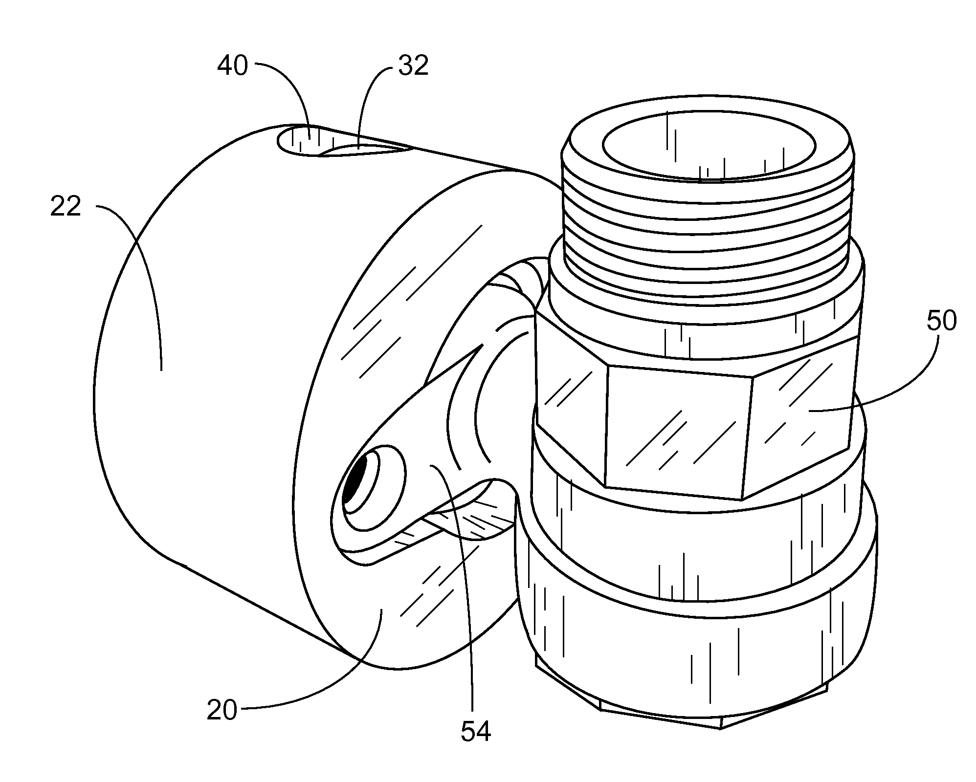
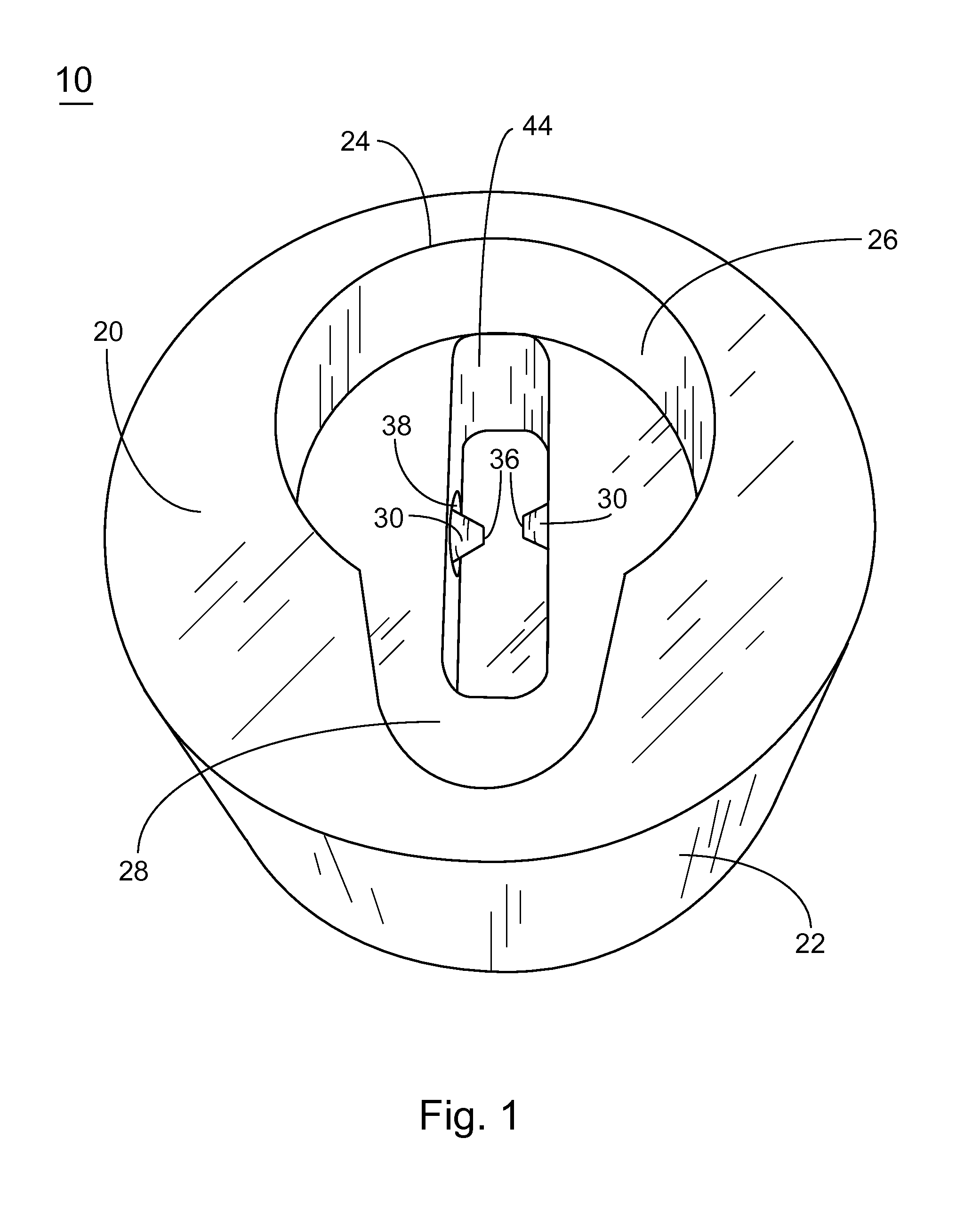
[0022]Turning now to the figures in which like reference characters indicate corresponding elements throughout the several views, there is shown a shut-off valve locking apparatus and method, generally designated by reference numeral 10, which consist of a cylindrical housing, generally designated by reference numeral 20, that serves as a security device and a set of screws, generally designated by reference numeral 30, which serve as a locking means to retain the housing 20 in position about a valve 50. As used herein, the word “bottom” corresponds to the receiving side o...


PUM

PropertyMeasurementUnit
quasi-circular shapeaaaaaaaaaa
structuresaaaaaaaaaa
sizeaaaaaaaaaa

Abstract

The present apparatus is a novel locking apparatus and method for use with a shut-off valve. The housing of the locking apparatus is configured to receive at least a portion of the shut-off valve and secure it in a closed or off position. The housing of the locking device envelopes the shut-off valve and is secured in placed through the use of two screws. The screws have proprietary head shapes having a matching key. By using a housing which envelopes the shut-off valve and screws with proprietary head shapes, conventional methods to gain unauthorized access to the shut-off valve, such as lock picks, lock cutters, hammers, pry bars, and the like are ineffective.

Description

BACKGROUND OF THE INVENTION[0001]1. Field of Invention[0002]The present invention relates to security devices and methods for locking valves routinely utilized to regulate the flow of material. More specifically, the present invention relates to an apparatus and method having an integrated locking mechanism, wherein the present invention is positionable over at least a portion of a valve to prevent the unauthorized use thereof.[0003]2. Description of the Related Art[0004]Valves are routinely utilized in industrial, military, commercial and residential settings to regulate, direct and / or control the flow of material by opening, closing or partially obstructing various passageways. One of the most common materials is water. In modern society, there are a multitude of water-use applications including, for example, flushing toilets, washing clothes, washing dishes, bathing, drinking, cooking and landscaping. At the consumer residential level, main valves which regulate the flow of water...

Claims


Application Information

Patent Timeline
Patent Type & Authority Applications(United States)
IPC IPC(8): F16K35/00B23P19/00
CPCY10T29/49826F16K35/10
Inventor BENNETT, DONNIE
Owner BENNETT DONNIE
Why Eureka
Try Eureka