Illumination device and inspection device of tire

Active Publication Date: 2012-05-31
NIHON KIZAI +1
View PDF32 Cites 69 Cited by
  • Summary
  • Abstract
  • Description
  • Claims
  • Application Information

AI Technical Summary

Benefits of technology

[0017]In the present invention, it is possible to easily

Problems solved by technology

In such a tire, in which linear concave and convex portions exist on the inner peripheral surface, there is a strong concern that the stability of the tire is low.
However, in the illumination device such as JP-A-2002-286645, there is a problem in that, in order to make the light intensity reflected from the inspection region of the inner peripheral surface of the tire uniform, shadows are not cast even when the linear concave and convex portions exist on the inner peripheral surface of the tire, and it is extremely difficult to detect an existence of the concave and convex portions.
In such a case, in order to increase a region that can be photographed in a circumferential direction of the tire, since the inner pe

Method used


Image

  • Illumination device and inspection device of tire
  • Illumination device and inspection device of tire
  • Illumination device and inspection device of tire

Examples


first embodiment

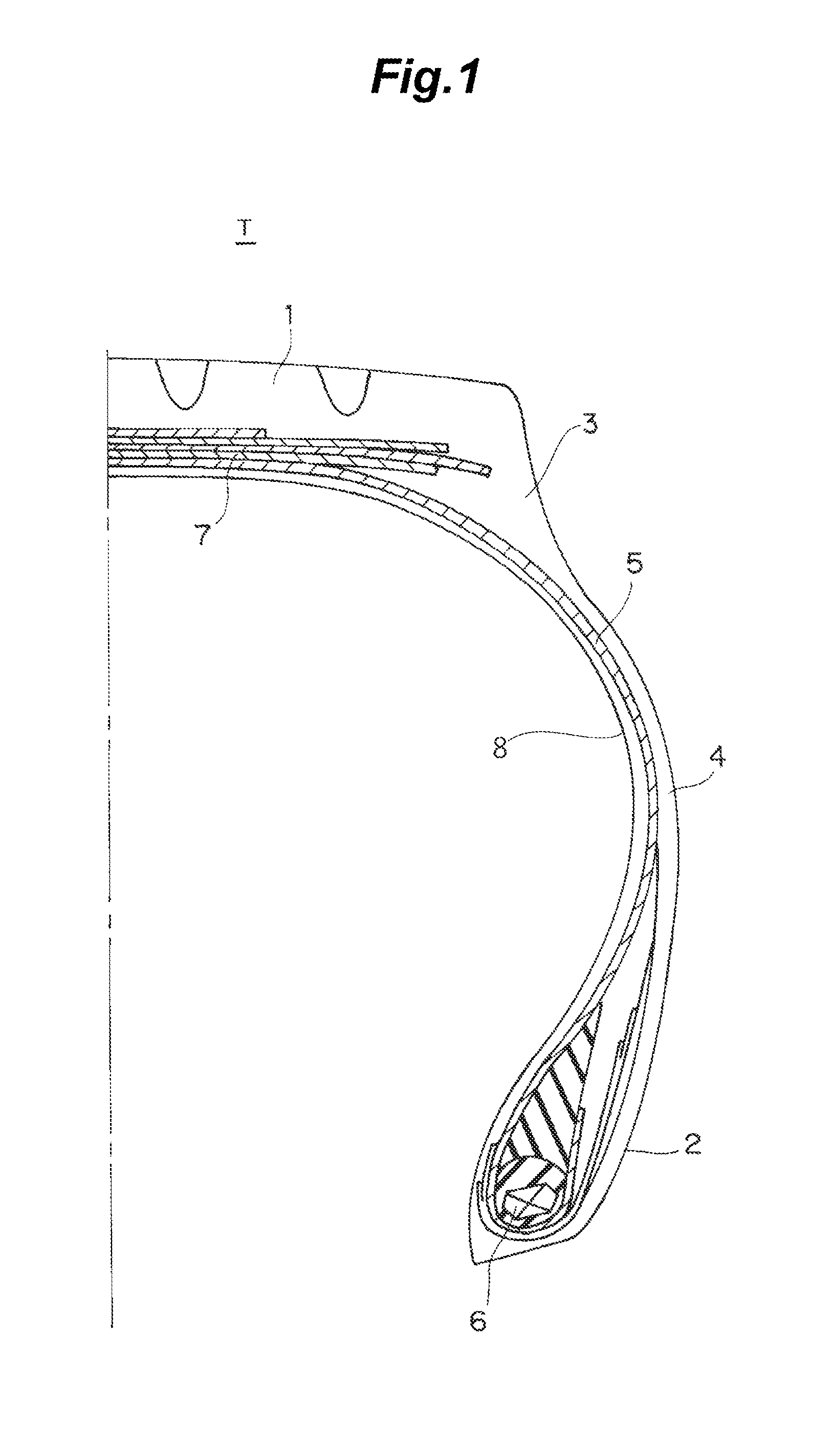
[0044]As shown in FIG. 1, a tire T as an inspection target in the present embodiment includes a tread portion 1, a pair of left and right bead portions 2, a pair of left and right shoulder portions 3 interposed between the tread portion 1 and the bead portions 2, and side wall portions 4. A carcass ply 5 is disposed inside the tread portion 1 in a radial direction, the carcass ply 5 being formed of one layer or a plurality of layers in which a steel cord or a high strength organic fiber cord is arranged in a tire radial direction. The carcass ply 5 is locked by being wound up from the inside of the bead core 6 to the outside thereof by the bead portion 2 from the tread portion 1 via both side wall portions 4. Furthermore, in the outside of the carcass ply 5 in the radial direction in the tread portion 1, a plurality of belts 7 formed of a steel cord is disposed.

[0045]The tire T having the above configuration is inspected as to whether or not linear concave or convex portions exceedi...

second embodiment

[0077]Next, a second embodiment will be described with reference to the drawings.

[0078]In the present embodiment, a tire T as an inspection target is the same as the tire T as the inspection target of the aforementioned first embodiment, and the detailed description thereof will be omitted herein.

[0079]A tire inspection device of a tire (hereinafter referred to as an inspection device) 110 of the present embodiment inspects whether or not a bulge called an air stagnation exists on the inner peripheral surface 8 of the tire T in the final stage of the manufacturing process.

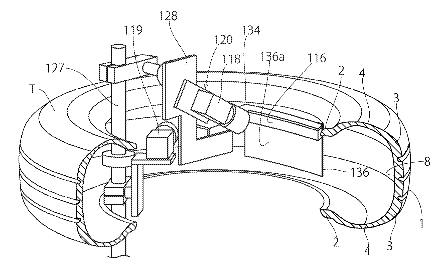
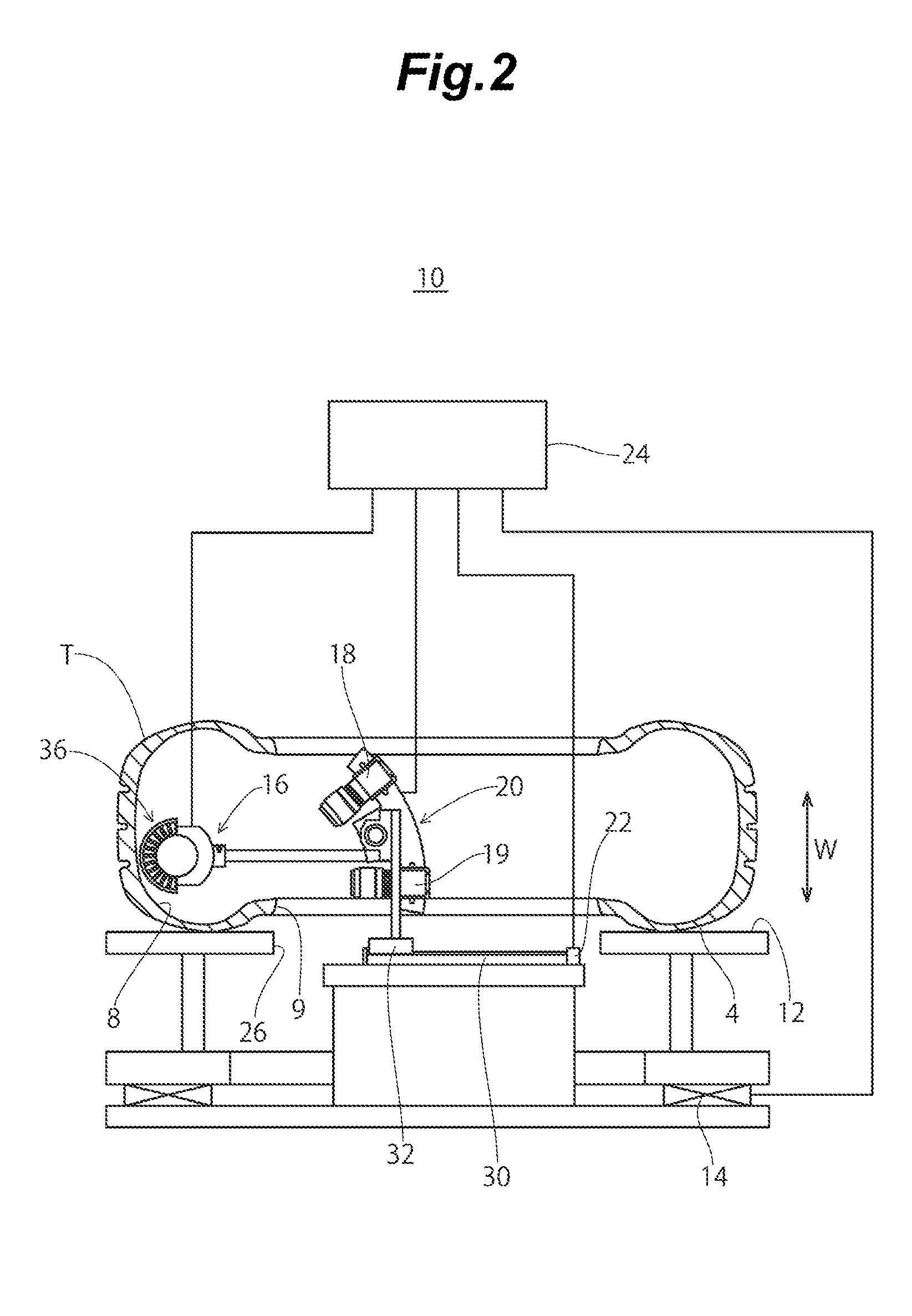
[0080]The inspection device 110 includes a rotation table 112 on which the tire T is placed with one side wall portion 4 directed downward; a table driving portion 114 that rotates the rotation table 112; an inspection portion 120 including a mirror 136, an illumination portion 116, a first photographing portion 118, and a second photographing portion 119; an inspection driving portion 122 that moves the inspection...

third embodiment

[0116]Next, a third embodiment will be described with reference to the drawings.

[0117]The tire T as an inspection target in the present embodiment is the same as the tire T as the inspection target of the first embodiment, and the detailed description thereof will be omitted herein.

[0118]An inspection device 210 of a tire (hereinafter referred to as an inspection device) in the present embodiment inspects the tire T while rotating the tire T, and as shown in FIGS. 14 and 15, a plurality (for example, three in the present embodiment) of inspection portions 220 and carry-out tables 240 is provided in a row at equal intervals.

[0119]Among the plurality of provided inspection portions 220, the tire T of the inspection target is placed on a first inspection portion 220a from the outside of the inspection device 210, the tire T transported from the first inspection portion 220a is placed on a second inspection portion 220b disposed adjacently to the first inspection portion 220a, and the t...


PUM


Abstract

Disclosed are an illumination device and an inspection device of a tire that can easily detect abnormality of the shape of the manufactured tire. A photographing portion 18,19 photographs a inner peripheral surface of a tire T, while a driving portion 12 relatively rotates the tire T and a inspection portion 20 around an axis of the tire T, in the state of irradiating a light from a light source unit 36 disposed along the inner peripheral surface of the tire T toward the circumferential direction of the tire T.

Description

BACKGROUND OF THE INVENTION[0001]1. Field of the Invention[0002]The present invention relates to an illumination device that illuminates an inner peripheral surface of a tire, and an inspection device of a tire.[0003]2. Background Art[0004]Normally, a tubeless tire is vulcanized and becomes a finished tire by stacking members such as an inner liner, a carcass, a belt, and a tread on a molding drum to mold a non-vulcanized tire, charging the same in a mold, performing an extended deformation by shaping using a bladder, and heating the same while pressing against a mold surface. In order to improve mold releasability from the bladder after vulcanizing, a water-soluble releasing agent or the like is applied to an inner liner of an inner surface of the non-vulcanized tire.[0005]In the manufactured tire, linear concave and convex portions extending in a tire width direction may appear on an inner peripheral surface of the tire due to irregularity of members and the like during manufactur...

Claims


Application Information

Patent Timeline
IPC IPC(8): G03B37/02G01N21/89F21V21/30
CPCG01N21/8901G01N21/95G01M17/027G06K9/00604A61B3/14A61B3/145A61B3/12G01N21/8806G01N21/954B60C25/002B60C25/0554B60C25/0512
Inventor MIZUKUSA, HIROKATSUNAKAMOTO, HITOSHIOTANI, WATARU
Owner NIHON KIZAI
Why Eureka
Try Eureka