Abnormality diagnostic device for power transmission mechanism and abnormality diagnostic method for power transmission mechanism
a technology of abnormality and diagnostic device, which is applied in the direction of electric testing/monitoring, vibration measurement in solids, instruments, etc., can solve the problems of deterioration progressing at an accelerating pace, and achieve the effects of low cost, easy detection of abnormalities, and easy detection
- Summary
- Abstract
- Description
- Claims
- Application Information
AI Technical Summary
Benefits of technology
Problems solved by technology
Method used
Image
Examples
embodiment 1
[0031]Hereinafter, a power transmission mechanism abnormality diagnostic device and a power transmission mechanism abnormality diagnostic method according to embodiment 1 of the present invention will be described with reference to the drawings.
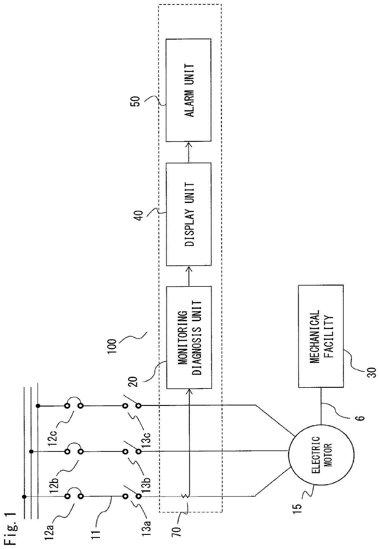
[0032]FIG. 1 is a diagram showing an electric motor 15 managed by a motor control center and the configuration of an abnormality diagnostic device 100 for detecting abnormality of a belt mechanism 6 (power transmission mechanism) which transmits power from the electric motor 15 to a mechanical facility 30 as a load.
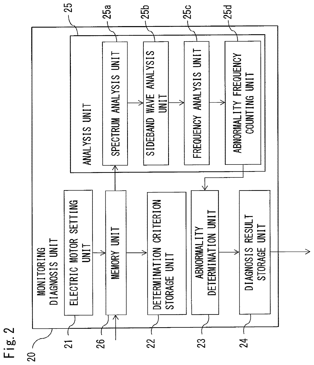
[0033]FIG. 2 is a diagram showing the configuration of a monitoring diagnosis unit 20 of the abnormality diagnostic device 100.
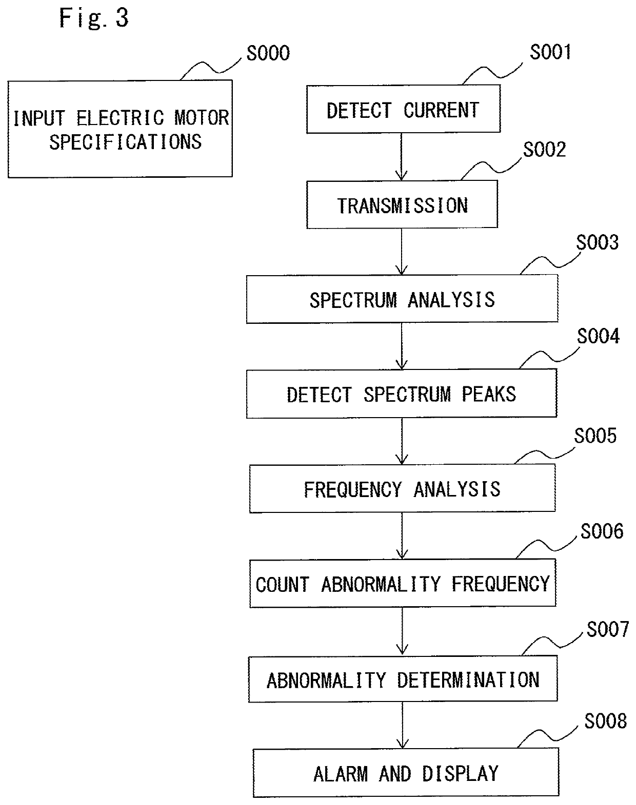
[0034]FIG. 3 shows a processing flow of the abnormality diagnostic device 100.
[0035]FIG. 14 shows the belt mechanism 6.
[0036]The belt mechanism 6 is configured such that a belt BE (power transmission member) is wound around a pulley Put connected to the rotary shaft of the electric motor 15 and a pulley Pu2...
embodiment 2
[0061]Hereinafter, with reference to the drawings, a power transmission mechanism abnormality diagnostic device and a power transmission mechanism abnormality diagnostic method according to embodiment 2 of the present invention will be described, focusing on difference from embodiment 1.
[0062]FIG. 6 is a diagram showing electric motors 15a, 15b, 15c managed by a motor control center and the configuration of an abnormality diagnostic device 200 (parts enclosed by two broken-line frames) for detecting abnormality of belt mechanisms 6a, 6b, 6c (power transmission mechanisms) which transmit powers from electric motors 15a to 15c to respective mechanical facilities 30a, 30b, 30c as loads.
[0063]FIG. 7 is a diagram showing the configuration of a monitoring diagnosis unit 220 of the abnormality diagnostic device 200.
[0064]FIG. 8 shows a processing flow of the abnormality diagnostic device 200 (in the case of a plurality of same-type electric motors).
[0065]The abnormality diagnostic device 2...
embodiment 3
[0074]Hereinafter, with reference to the drawings, a power transmission mechanism abnormality diagnostic device and a power transmission mechanism abnormality diagnostic method according to embodiment 3 of the present invention will be described, focusing on difference from embodiment 1.
[0075]FIG. 10 is a diagram showing an electric motor 15 managed by a motor control center and the configuration of an abnormality diagnostic device 300 for detecting abnormality of the belt mechanism 6 (power transmission mechanism) which transmits power from the electric motor 15 to a mechanical facility 30 as a load.
[0076]FIG. 11 is a diagram showing the configuration of a monitoring diagnosis unit 320 of the abnormality diagnostic device 300.
[0077]FIG. 12 shows a processing flow of the abnormality diagnostic device 300.
[0078]Difference between embodiment 1 and embodiment 3 is that an electric motor drive control device 80 is provided to the three-phase power supply.
[0079]The current detector 70 ma...
PUM
 Abstract
Description
Claims
Application Information
 - R&D
- Intellectual Property
- Life Sciences
- Materials
- Tech Scout
- Unparalleled Data Quality
- Higher Quality Content
- 60% Fewer Hallucinations
Browse by: Latest US Patents, China's latest patents, Technical Efficacy Thesaurus, Application Domain, Technology Topic, Popular Technical Reports.
© 2025 PatSnap. All rights reserved.Legal|Privacy policy|Modern Slavery Act Transparency Statement|Sitemap|About US| Contact US: help@patsnap.com


