Device and method for detecting abnormality of joint of parallel link robot

a technology of parallel link robot and abnormality detection, which is applied in the direction of programmed manipulators, instruments, programme control, etc., can solve the problems of excessive friction force of ball joints, inability to smoothly perform sliding motion of ball joints, and increased torque of drive motors, so as to achieve the effect of easy detection of abnormalities

Inactive Publication Date: 2017-12-07
FANUC LTD +1
View PDF0 Cites 11 Cited by
  • Summary
  • Abstract
  • Description
  • Claims
  • Application Information

AI Technical Summary

Benefits of technology

[0010]Therefore, an object of the present invention is to provide a device and method for easily detecting an abnormality of a joint part of a delta-type parallel link robot having a link ball structure, by estimating a friction torque (sliding wear) of a ball joint of the robot.

Problems solved by technology

Further, when a foreign substance enters a ball sliding portion of the link ball, the sliding motion of the ball joint cannot be smoothly performed, and the friction force thereof may be excessively increased.
When the friction force of the ball joint is excessively increased, a torque of the drive motor is also increased.
As a result, continuous motion performance of the robot may be deteriorated, an excess load may be applied to each component of the link structure, and / or excess heat may be generated at the ball joint, whereby an unexpected malfunction may occur.
Generally, a delta-type robot is used when high-speed motion is required, and thus a hand or peripheral equipment of the robot may be seriously damaged if the above malfunction occurs.
It may be difficult to detect an abnormality of the ball joint of the delta-type parallel link robot by using the method of JP 2005-186183 A or JP 2006-281421 A, since the ball joint of the delta-type parallel link robot is a passive joint which follows the posture of the robot, and is positioned away from the drive side (drive motor), and thus it is difficult to detect the friction state of the passive joint.

Method used


Image

  • Device and method for detecting abnormality of joint of parallel link robot
  • Device and method for detecting abnormality of joint of parallel link robot
  • Device and method for detecting abnormality of joint of parallel link robot

Examples


Embodiment Construction

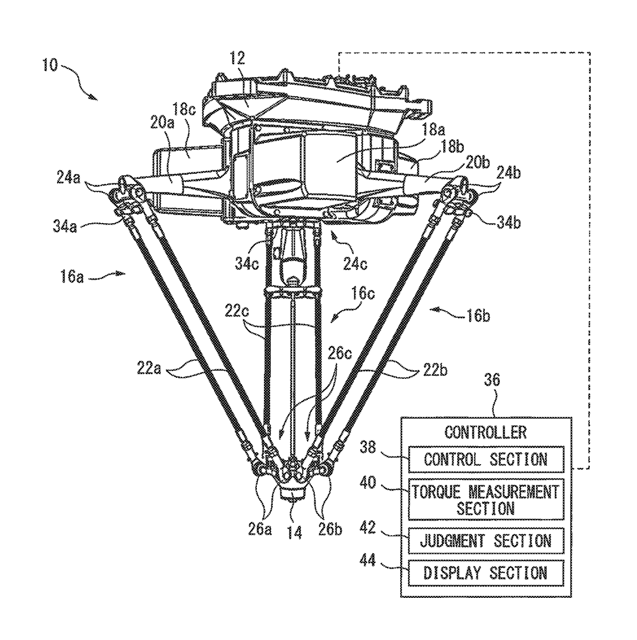
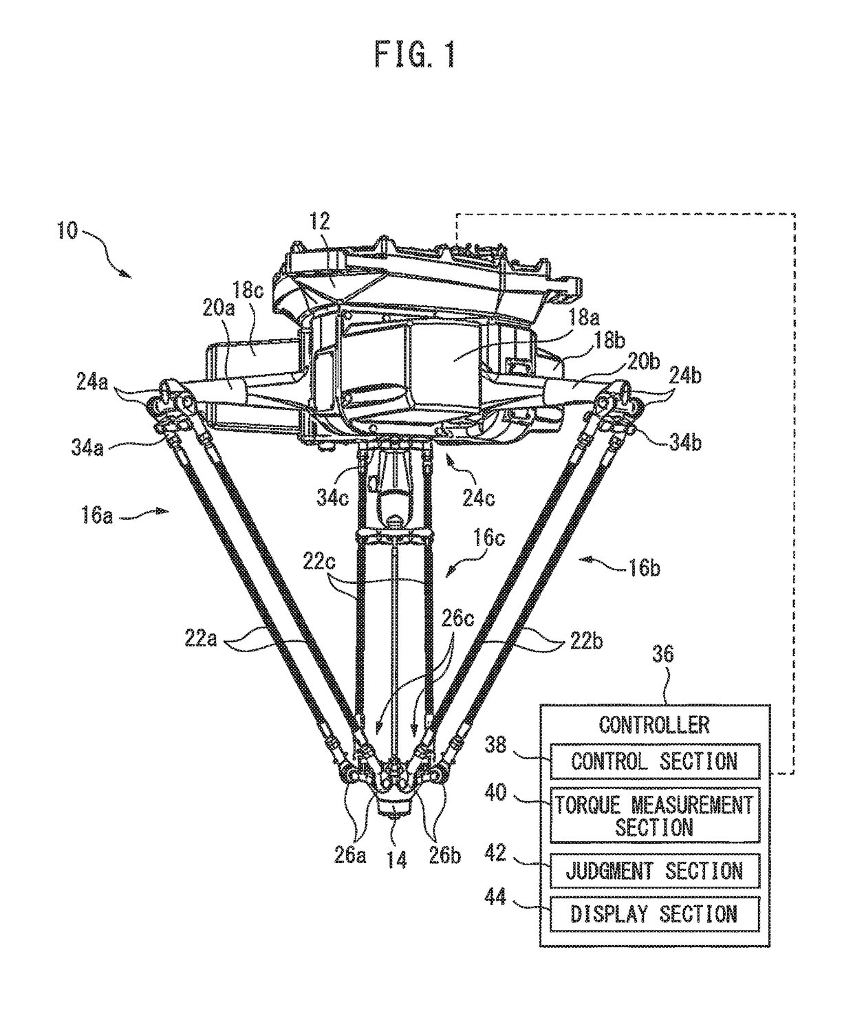
[0023]FIG. 1 is a view showing a schematic configuration of a delta-type parallel link robot 10, to which a method and device for detecting an abnormality according to a preferred embodiment of the present invention can be applied. Parallel link robot 10 has a base part 12; a movable part 14 positioned away from (normally, positioned below) base part 12; two or more (in the illustrated embodiment, three) link parts 16a, 16b and 16c which connect movable part 14 to base part 12, each link part including one degree-of-freedom relative to base part 12; and a plurality of (normally the same number as the link parts, and in the illustrated embodiment, three) motors 18a, 18b and 18c which respectively drive link parts 16a, 16b and 16c. To movable part 14, an end effector (schematically shown in FIGS. 6 and 7) such as a robot hand can be attached.

[0024]Link part 16a is constituted by a drive link 20a connected to base part 12 and a pair of (two) passive links 22a which extend parallel to e...


PUM


Abstract

A device and method for easily detecting an abnormality of a joint part of a delta-type parallel link robot having a link ball structure, by estimating a friction torque of a ball joint of the robot. A controller of the robot has: a control section configured to control the motion of the robot; a torque measurement section configured to measure or calculate, during the robot is operated, an amount of change in a drive torque, based on a current value of the motor, before and after the robot represents a specified posture where a sign of a relative angular velocity between a ball and a housing of the ball joint is changed; and a judgment section configured to judge that, when the measured amount of change in the drive torque exceeds a predetermined threshold, a friction state of the ball joint corresponding to the motor is abnormal.

Description

BACKGROUND OF THE INVENTION1. Field of the Invention[0001]The present invention relates to a device and method for detecting an abnormality of a joint of a parallel link robot.2. Description of the Related Art[0002]As means for positioning a movable part having an end effector in three-dimensions, a parallel link robot having a delta-type parallel link mechanism is well known. The delta-type parallel link robot has a base part, a movable part, and a drive link and a passive (driven) link for connecting the movable part to the base part. In many cases, the parallel link robot has three pairs of drive links and passive links, and the movable part can be moved with three degrees-of-freedom (X, Y, Z) by individually controlling the motion of each pair.[0003]Generally, the passive link and the drive link are connected via a ball joint having three degrees-of-freedom, and the passive link and the movable part are also connected via a ball joint having three degrees-of-freedom. For example...

Claims


Application Information

Patent Timeline
Patent Type & Authority Applications(United States)
IPC IPC(8): B25J9/16B25J19/02B25J9/00
CPCB25J9/1633B25J19/02Y10T74/20329B25J9/1676B25J9/0051B25J9/1664B25J17/0275B25J19/0095B25J19/06G05B19/406B25J9/1674G05B2219/37373
Inventor ABE, KENICHIROWU, YUNFENGYAMASHIRO, HIKARUTAKEDA, YUKIOSUGAHARA, YUSUKEMATSUURA, DAISUKEOHNO, MASUMI
Owner FANUC LTD
Why Eureka
Try Eureka