Mechanism for modulating diffuser vane of diffuser

Active Publication Date: 2012-05-31
IND TECH RES INST
View PDF14 Cites 11 Cited by
  • Summary
  • Abstract
  • Description
  • Claims
  • Application Information

AI Technical Summary

Benefits of technology

[0009]Accordingly, the present invention allows the actuator to be installed outside of the compressor, and is characterized by the correlative movements of the actuator, the driving shaft, the driving wheel and the driving ring along the shaft in a radial direction to diametrically transmit dynamic power to rotate the diffuser vane sh

Problems solved by technology

However, there still exist several disadvantages in the foregoing approaches including space-consuming, complex assembly and burdensome maintenance.
Besides the drawbacks of having complex structures, both the foregoing applications adopt transmitting power of the actuator along the compressor axle, which requires actuators to be disposed in the compressor.
In so doing, not only it requires the design and reservation of a relatively larger space

Method used


Image

  • Mechanism for modulating diffuser vane of diffuser
  • Mechanism for modulating diffuser vane of diffuser
  • Mechanism for modulating diffuser vane of diffuser

Examples


Embodiment Construction

[0016]The following illustrative embodiments are provided to illustrate the disclosure of the present invention, these and other advantages and effects can be understood by persons skilled in the art after reading the disclosure of this specification.

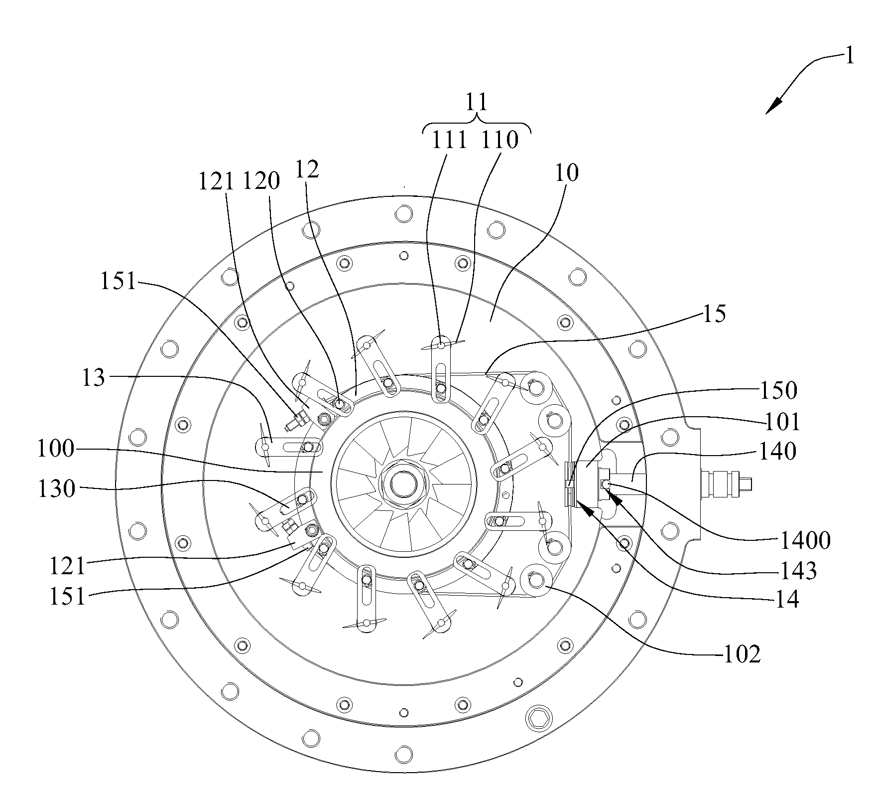
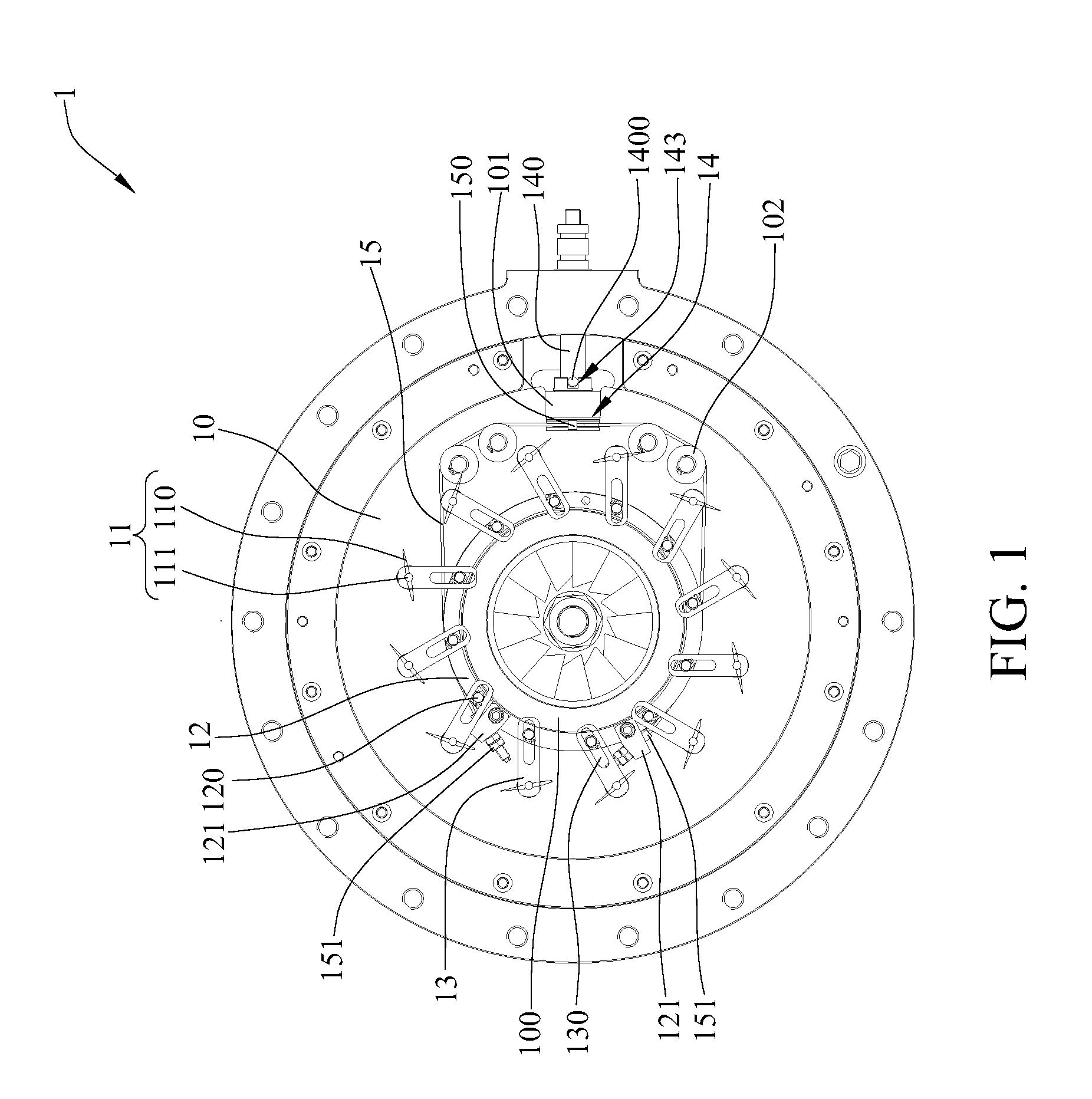
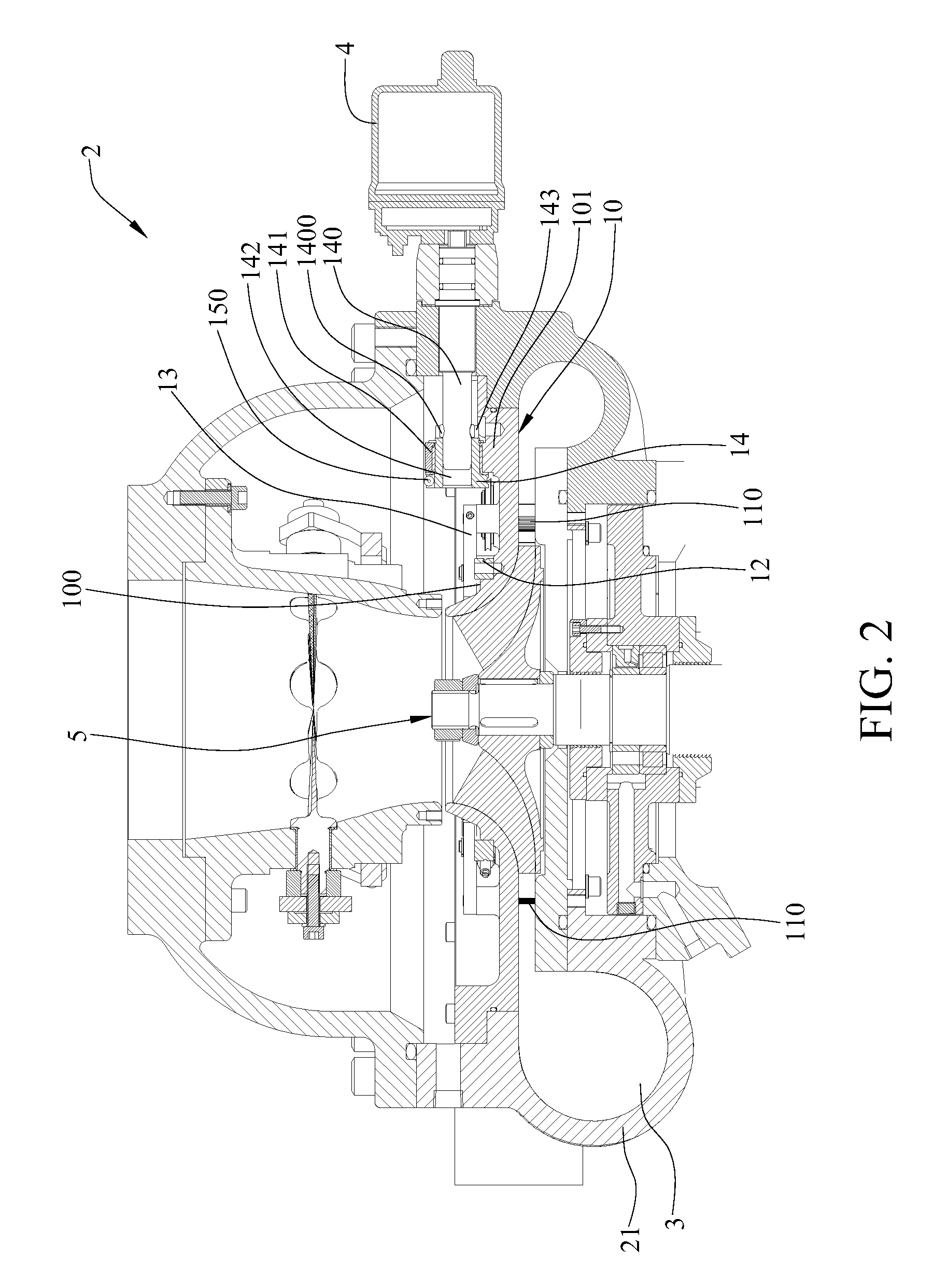
[0017]FIGS. 1, 2, 3, 4 and 5 illustrate the mechanism for modulating the diffuser vane of a compressor diffuser of the present invention. FIG. 1 is a top view of the mechanism for modulating the diffuser vane disposed in a compressor diffuser according to the present invention. FIG. 2 is a cross-sectional view of the diffuser vane of a compressor diffuser according to the present invention. FIG. 3 is a locally enlarged view of the mechanism for modulating the diffuser vane of a compressor diffuser according to the present invention. FIG. 4 is a cross-sectional view of the diffuser vane of the modulating mechanism according to the present invention. FIG. 5 is a cross-sectional view of the driving cable of the modulating mechanism in acco...


PUM


Abstract

A mechanism modulates a fluid flow in a diffuser flow path of a compressor diffuser, including: a shroud disposed on the diffuser flow path and having a cam and a driving wheel fixed base; a diffuser vane having a diffuser guide vane disposed in the diffuser flow path and a diffuser vane shaft fixedly disposed on the diffuser vane that penetrates from the diffuser flow path through the shroud; a driving ring sleeved on the cam and having a moving bar; a sliding block having one end connected with one end the diffuser vane shaft that penetrates through the shroud, and the other end sleeved on a sliding groove formed on the moving bar; a driving wheel disposed in the driving wheel fixed base and having a driving shaft connected to an actuator outside of the compressor; and a driving cable connected to the driving wheel and the driving ring.

Description

BACKGROUND[0001]1. Field of the Invention[0002]The present invention relates to a mechanism for modulating the diffuser vane of a compressor diffuser, and, more particularly, to a mechanism that modulates the disposition of diffuser vanes in a compressor diffuser by means of radial power transmission.[0003]2. Description of Related Art[0004]In order to suppress a compressor surge and to expand operating ranges of low negative loads, diffuser vanes have been brought into the design mainstream to dynamically alter the flow direction of the flow path in a compressor diffuser. For instance, U.S. Pat. No. 5,116,197 disclosed a technique of disposing diffuser vanes in a compressor, in which the actuator transmits the power through a plurality of connectors, including rolling balls, connecting poles, cams and driving rings, to diffuser vanes, in order to modulate disposal angles thereof in the flow path of the compressor diffuser, which in turn dynamically changes the direction of flowing ...

Claims


Application Information

Patent Timeline
IPC IPC(8): F04D29/56
CPCF04D29/4213F01D17/165F04D29/462F05D2250/51F05D2250/52
Inventor YEN, CHENG-CHUNGCHIANG, CHUNG-PINGCHEN, CHING-FUCHOW, YUNG-LO
Owner IND TECH RES INST
Why Eureka
Try Eureka