Drawable housing structure

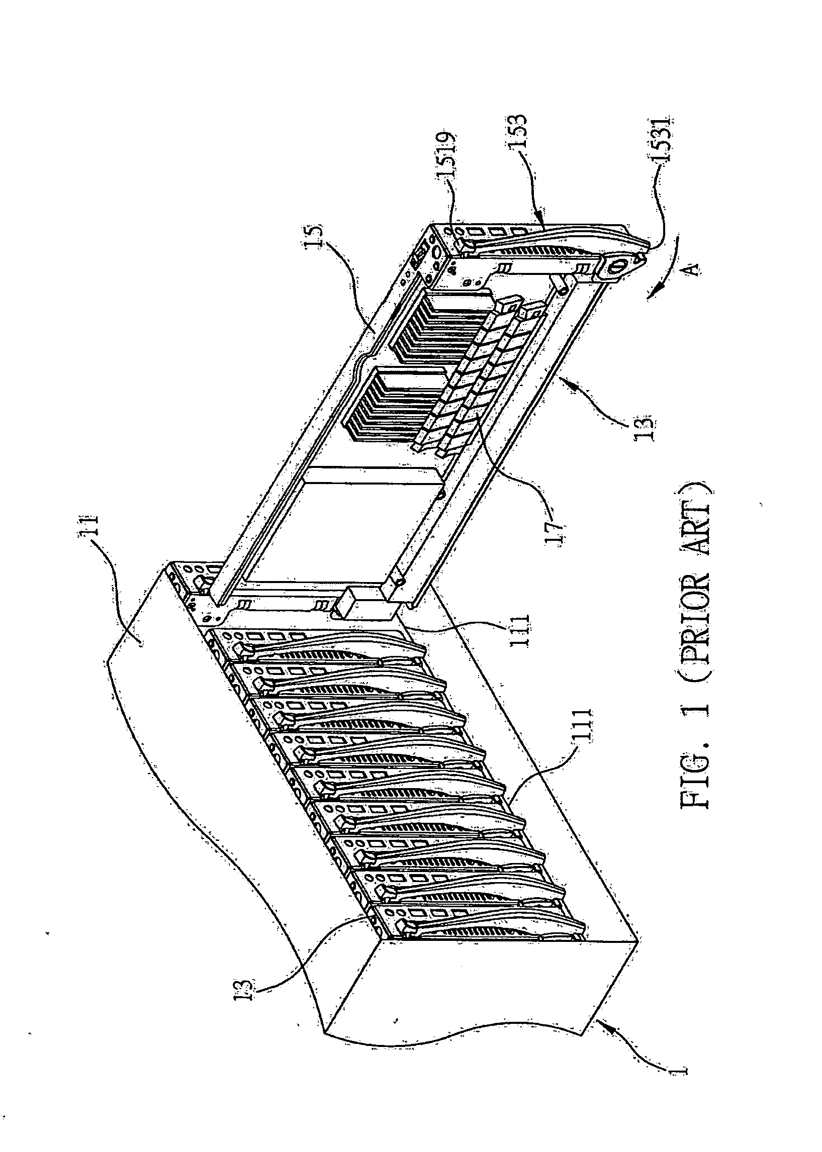
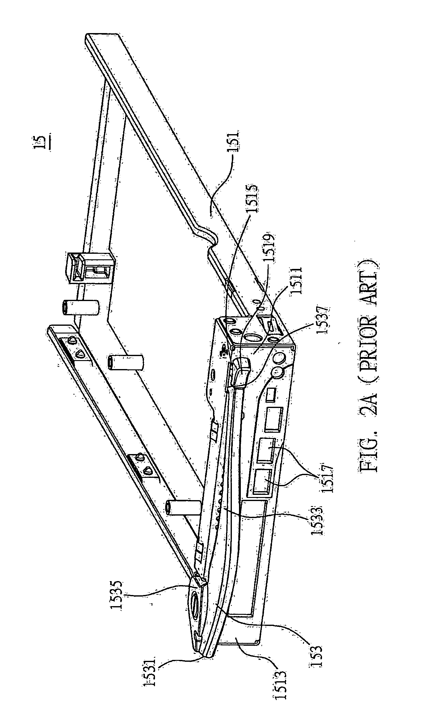
a housing structure and drawing technology, applied in the direction of support structure mounting, cabinet, card stiffener, etc., can solve the problems of inconvenient and complicated assembly/detachment process of prior art, and the sudden popping of the pull rod 153/b> likely hurting users, so as to simplify the assembly and detachment process, the effect of less space consumption

Inactive Publication Date: 2007-10-04
INVENTEC CORP
View PDF13 Cites 0 Cited by
  • Summary
  • Abstract
  • Description
  • Claims
  • Application Information

AI Technical Summary

Benefits of technology

[0021] In summary, the present invention have the advantages of labor-saving, less space consumption, simplified assembly and detachment processes. Moreover, the present invention is safe in use, and solve the drawbacks of the prior art.

Problems solved by technology

Such the assembly / detachment processes of the prior art are complicated and inconvenient.
Moreover, the suddenly popping of the pull rod 153 likely hurts users.

Method used


Image

  • Drawable housing structure
  • Drawable housing structure
  • Drawable housing structure

Examples


Embodiment Construction

[0029] The following illustrative embodiments are provided to illustrate the disclosure of the present invention, these and other advantages and effects can be apparently understood by those in the art after reading the disclosure of this specification. The present invention can also be performed or applied by other different embodiments. The details of the specification may be on the basis of different points and applications, and numerous modifications and variations can be devised without departing from the spirit of the present invention.

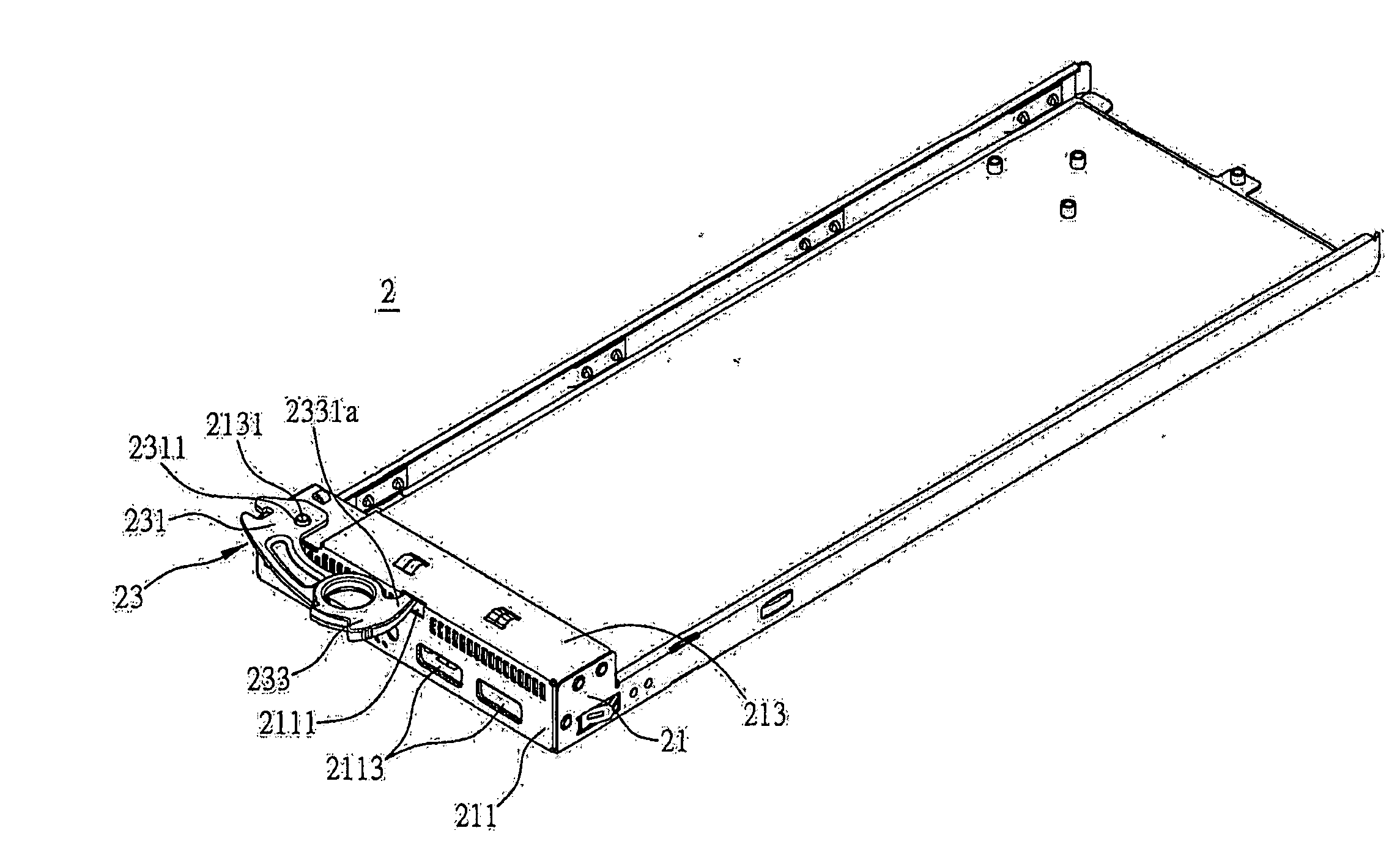
[0030] Please refer to FIG. 3A to FIG. 4. FIG. 3A is a schematic diagram of a drawable housing structure 2 of the preferred embodiment according to the present invention. FIG. 3B and FIG. 3C are two operating states of the housing structure 2. FIG. 4 is an explosive view of a handler 23 of the housing structure 2. The housing structure 2 can be installed in an electronic device for supporting a plurality of electronic components of the electron...


PUM


Abstract

A drawable housing structure is applicable to an electronic device for supporting a plurality of electronic components of the electronic device. The housing structure includes a main body for supporting the electronic components. The main body includes a front surface having an opening, and a top surface connected to the front surface and having a first opening. The housing structure further includes a handler. The handler includes a cantilever engaged with the first opening, and a rotatable fixing member engaged with the cantilever for buckling the opening. By drawing the rotatable fixing member the cantilever moves accordingly, and the housing structure can be took out from the electronic.

Description

BACKGROUND OF THE INVENTION [0001] 1. Field of the Invention [0002] This invention relates to drawable housing structures, and more particularly, to a drawable housing structure applicable to an electronic device. [0003] 2. Description of Related Art [0004] With the development of information technologies, computers are allowed to operate at a very fast speed but have low cost. A computer has wide application. For example, a computer server having a plurality of complicated functions can be applied to an enterprise, while a personal computer is designed for individuals. A computer server comprises a main board, a hard drive and a plurality of electronic components, such as a central processing unit (CPU), a chip set and a memory, all of which are installed on the main board. The server computer operates individually and is replaceable. The server computer can be integrated on a rack, and becomes one of a plurality of serially connected and stacked disposed server computers of a serv...

Claims


Application Information

Patent Timeline
Patent Type & Authority Applications(United States)
IPC IPC(8): A47B88/00
CPCH05K7/1461
Inventor CHEN, JUI-LINHSU, WEI-CHUAN
Owner INVENTEC CORP
Why Eureka
Try Eureka